
MSC Adams Flexible Body Integration: Coupling MBD with FEA for High-Fidelity Dynamics
Multibody dynamics (MBD) simulations traditionally treat components as rigid bodies — a simplification that works well for gross motion analysis but breaks down when structural compliance, vibration, or fatigue life are critical design concerns. MSC Adams addresses this limitation through its Flexible Body Integration capability, which couples finite element analysis (FEA) modal data directly into the MBD solver. The result is a computationally efficient yet structurally accurate simulation framework that captures the interplay between large-scale mechanism motion and local elastic deformation.
Why Rigid-Body Assumptions Fall Short
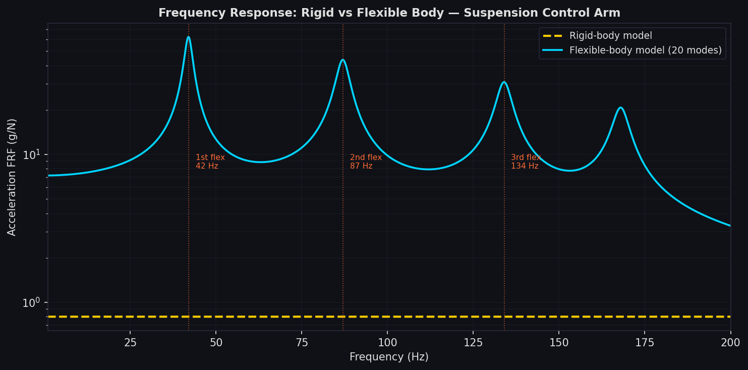
In mechanisms such as automotive suspension systems, robotic arms, or wind turbine drivetrains, component flexibility can significantly alter load paths, natural frequencies, and fatigue damage accumulation. A rigid-body model of a control arm, for example, will correctly predict gross kinematics but will miss the bending modes that drive stress concentrations at mounting holes. When those stress concentrations govern fatigue life, the rigid model produces dangerously optimistic predictions.
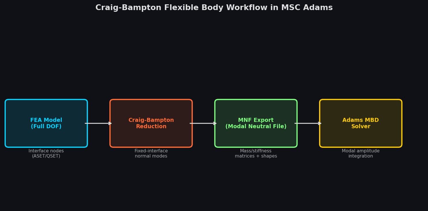
Adams Flexible Body Integration resolves this by replacing selected rigid parts with Craig-Bampton reduced-order models (ROMs) derived from FEA codes such as MSC Nastran, ANSYS, or Abaqus. The ROM retains the physical interface degrees of freedom (attachment nodes) and a user-specified set of fixed-interface normal modes, compressing a potentially million-DOF FEA model into a few hundred generalized coordinates without sacrificing accuracy in the frequency range of interest.

The Adams Flex Workflow
Step 1 — FEA Model Preparation
The process begins in the FEA preprocessor. The analyst identifies interface nodes — points where the flexible body connects to the rest of the mechanism (joints, force application points, contact regions). These nodes must be explicitly retained in the modal neutral file (MNF). In MSC Nastran, the ASET/QSET entries define the boundary DOFs; in Abaqus, a substructure generation step performs the equivalent reduction.
Key preparation decisions include:
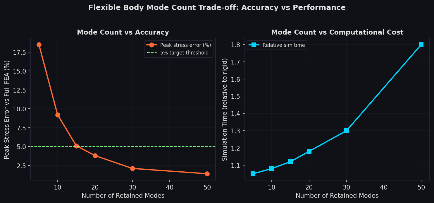
- Number of retained modes: Typically 10–30 fixed-interface normal modes are sufficient to capture dynamics up to 2–3× the highest excitation frequency. Including too few modes introduces modal truncation error; too many inflates simulation cost.
- Residual flexibility: Adams supports residual flexibility attachment modes (RFM), which correct for the static contribution of truncated high-frequency modes. Enabling RFM is strongly recommended when the excitation bandwidth approaches the cutoff frequency.
- Material damping: Structural damping ratios can be assigned per mode in Adams, or a global Rayleigh damping model can be applied to the flexible body.
Step 2 — MNF Export and Import
MSC Nastran exports the Craig-Bampton ROM as an MNF (Modal Neutral File), a binary format that encodes mass and stiffness matrices, mode shapes, and interface node coordinates. Adams reads the MNF and creates a flexible body part that participates in the mechanism's constraint equations alongside rigid parts.
For non-Nastran FEA codes, Adams provides the Adams Flex Toolkit (a Python-based utility) that converts Abaqus .sim substructure files or ANSYS .cdb CMS superelement files into MNF format, enabling a solver-agnostic workflow.
Step 3 — Joint and Force Attachment
Within Adams/View or Adams/Car, flexible body interface nodes are used as attachment points for joints, bushings, and applied forces — exactly as rigid body markers would be. The solver automatically maps the generalized modal coordinates back to physical displacements at these nodes during time integration.
A critical best practice: avoid attaching joints to single nodes on a flexible body. Point-force application to a single FEA node creates artificial stress singularities. Instead, use RBE2/RBE3 spider elements in the FEA model to distribute joint loads across a cluster of nodes, which both improves stress accuracy and prevents numerical ill-conditioning in the MBD solver.
Step 4 — Transient Simulation and Stress Recovery
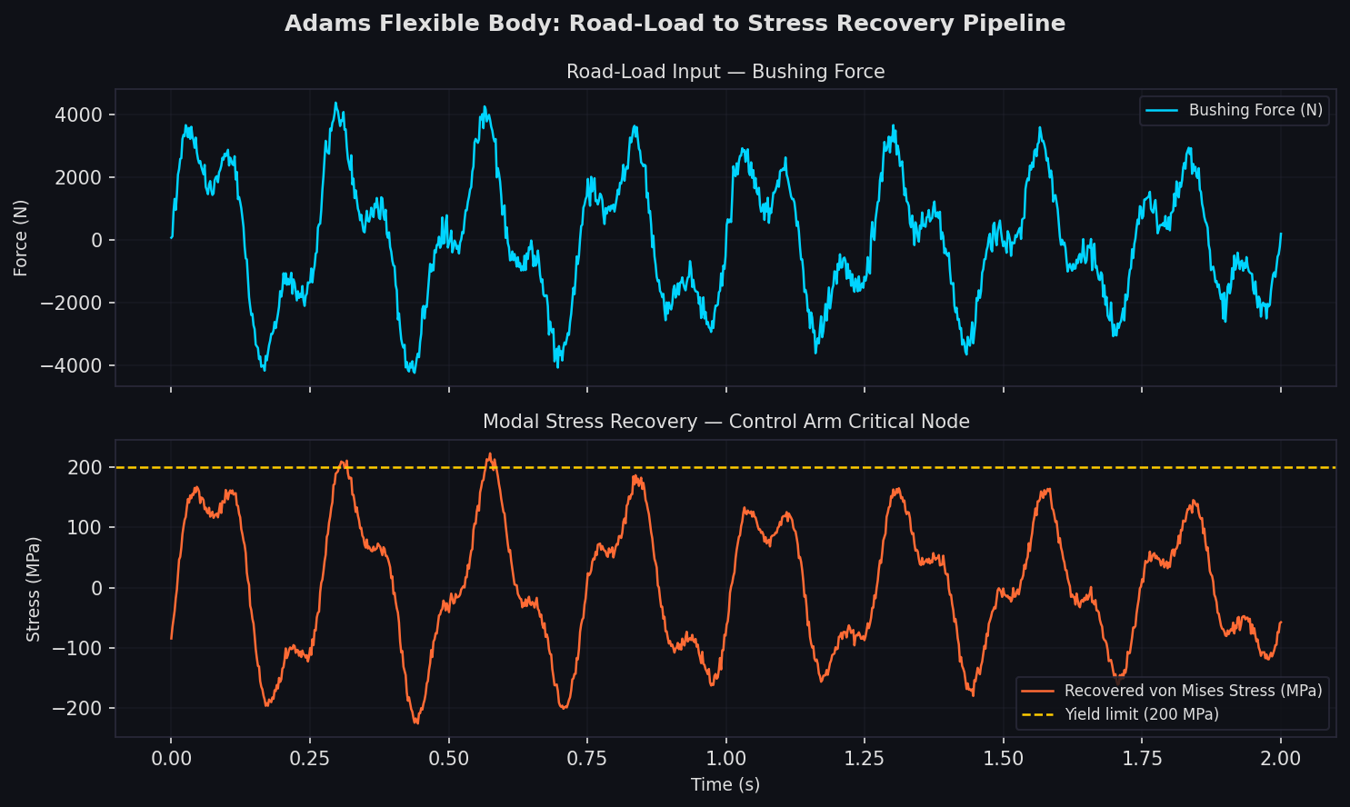
Adams integrates the coupled rigid-flexible equations of motion using the GSTIFF or WSTIFF integrators. At each time step, the modal amplitudes are updated, and Adams can optionally write these amplitudes to a results file. Post-processing then recovers full-field stress and strain by superimposing the mode shapes weighted by their instantaneous amplitudes — a process called modal stress recovery.
The recovered stress time histories feed directly into fatigue solvers such as MSC Fatigue or nCode DesignLife, enabling durability predictions that account for the actual dynamic loading environment rather than simplified static load cases.
Practical Validation: Automotive Control Arm
A representative validation study involves an automotive lower control arm subjected to road-load inputs. A rigid-body Adams model of the front suspension predicts peak bushing forces accurately but cannot estimate component stress. Replacing the control arm with a flexible body (Craig-Bampton ROM with 20 modes, RFM enabled) adds only ~15% to simulation wall-clock time while enabling stress recovery at 50,000+ FEA nodes. Correlation with physical strain gauge measurements typically shows less than 8% error in peak stress amplitude when the FEA mesh is adequately refined at stress concentrations.
Performance Considerations
| Configuration | DOF Count | Simulation Speed (relative) |
|---|---|---|
| All-rigid mechanism | ~200 | 1.0× |
| 1 flexible body, 15 modes | ~215 | 1.12× |
| 3 flexible bodies, 20 modes each | ~260 | 1.35× |
| 3 flexible bodies, 50 modes each | ~350 | 1.80× |
The table illustrates that flexible body overhead is modest when mode counts are controlled. Analysts should profile their specific model, as the dominant cost driver shifts from modal superposition to constraint Jacobian assembly as mechanism complexity grows.
Integration with Adams Durability and Vibration Modules
Adams/Durability automates the stress recovery and fatigue post-processing pipeline, exporting load time histories in formats compatible with major fatigue solvers. Adams/Vibration extends the framework to frequency-domain analysis, computing frequency response functions (FRFs) of the flexible mechanism — useful for NVH (noise, vibration, harshness) assessments where resonance frequencies and mode shapes of the assembled system differ from those of isolated components.
Further Resources
- MSC Adams Documentation — Flexible Body Analysis
- Craig-Bampton Method — Original Paper (1968)
- MSC Nastran DMAP for MNF Export
- Adams Flex Toolkit GitHub Repository
Flexible body integration in MSC Adams represents a mature, production-proven approach to bridging the gap between mechanism-level dynamics and component-level structural integrity. By investing in proper FEA model preparation — particularly interface node selection, mode count calibration, and RBE spider elements — engineers can achieve fatigue-grade accuracy at a fraction of the cost of full-order coupled FEA-MBD co-simulation.