

PSIM: Power Electronics Circuit Simulation and Motor Drive Design for Practicing Engineers
Power electronics engineers face a persistent challenge: circuit simulators built for general-purpose analog design struggle with the switching speeds, non-linear device behavior, and control-loop interactions that define modern converters. PSIM, developed by Powersim Inc., addresses this gap with a dedicated simulation environment optimized for switched-mode power supplies, motor drives, and renewable energy power stages. This article examines PSIM's core architecture, its motor drive simulation workflow, the SmartCtrl automated compensator design tool, and best practices for achieving fast, accurate results in production design cycles.
Why a Dedicated Power Electronics Simulator?
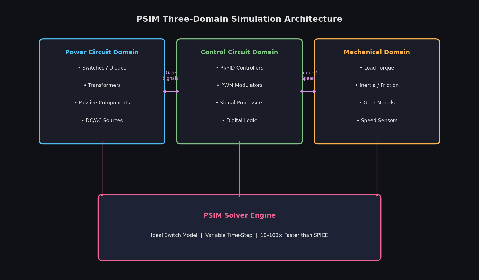
General SPICE-based tools model every transistor switching event at the device level, which produces accurate waveforms but imposes severe simulation time penalties on high-frequency converters. A 100 kHz boost converter running for 10 ms of steady-state time requires millions of time steps in a SPICE engine. PSIM uses ideal switch models with user-defined on-resistance and forward voltage, reducing the stiffness of the differential equations and enabling simulation speeds 10–100× faster than SPICE for the same converter topology. The trade-off — loss of sub-nanosecond switching transients — is acceptable for the vast majority of control-loop, thermal, and system-level studies.
PSIM's schematic environment is organized around three simulation domains that can coexist in a single schematic:

- Power circuit domain: switches, diodes, passive components, transformers, and machine models
- Control circuit domain: analog and digital control blocks, PWM modulators, and signal processing elements
- Mechanical domain: load torque, inertia, friction, and gear models for motor drive systems
This separation mirrors how engineers think about converter design and makes it straightforward to swap control topologies without rebuilding the power stage.
Motor Drive Simulation Workflow
PSIM ships with a comprehensive library of electric machine models covering DC machines, induction motors (squirrel-cage and wound-rotor), permanent-magnet synchronous motors (PMSM), brushless DC (BLDC) motors, and switched reluctance machines. Each model is available in both the d-q reference frame (for control design) and the phase-variable form (for detailed waveform analysis including harmonic content).
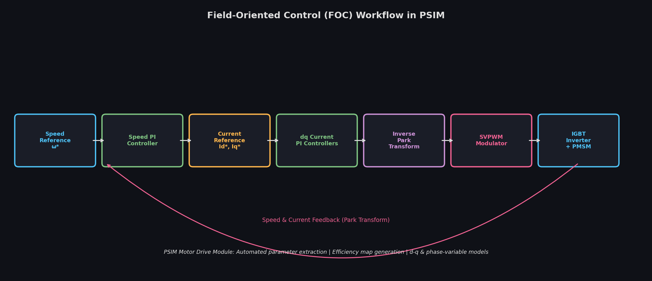
A typical PMSM field-oriented control (FOC) study proceeds as follows:
- Place the PMSM model and enter nameplate parameters: rated power, pole pairs, stator resistance, d- and q-axis inductances, and flux linkage constant.
- Build the inverter stage using PSIM's three-phase IGBT bridge with a DC bus capacitor and a voltage source representing the battery or DC link.
- Implement the FOC control block diagram: speed PI controller → current reference generation → d-q current PI controllers → inverse Park transform → space-vector PWM (SVPWM) modulator.
- Connect the mechanical load: a constant torque source for steady-state analysis, or a speed-dependent load profile for dynamic testing.
- Run the simulation and use the PSIM waveform viewer to inspect phase currents, d-q axis currents, torque ripple, and speed response.
PSIM's Motor Drive Module extends this workflow with automated parameter extraction from motor datasheets and a built-in efficiency map generator that sweeps speed and torque operating points to produce the 2-D efficiency contour maps required for EV powertrain studies.
SmartCtrl: Automated Compensator Design
Closing a stable feedback loop around a switching converter requires knowledge of the plant transfer function — the small-signal relationship between duty cycle and output voltage. PSIM's SmartCtrl add-on automates this process:
- AC sweep: SmartCtrl injects a small sinusoidal perturbation at the modulator input and measures the resulting output variation across a user-defined frequency range (typically 10 Hz to half the switching frequency). The result is a Bode plot of the open-loop plant.
- Compensator synthesis: the engineer specifies target crossover frequency and phase margin; SmartCtrl synthesizes a Type II or Type III compensator and displays the resulting closed-loop Bode plot.
- Digital implementation: SmartCtrl exports the compensator as a discrete-time transfer function with user-selected sampling rate and coefficient quantization, ready for direct implementation in a DSP or FPGA.
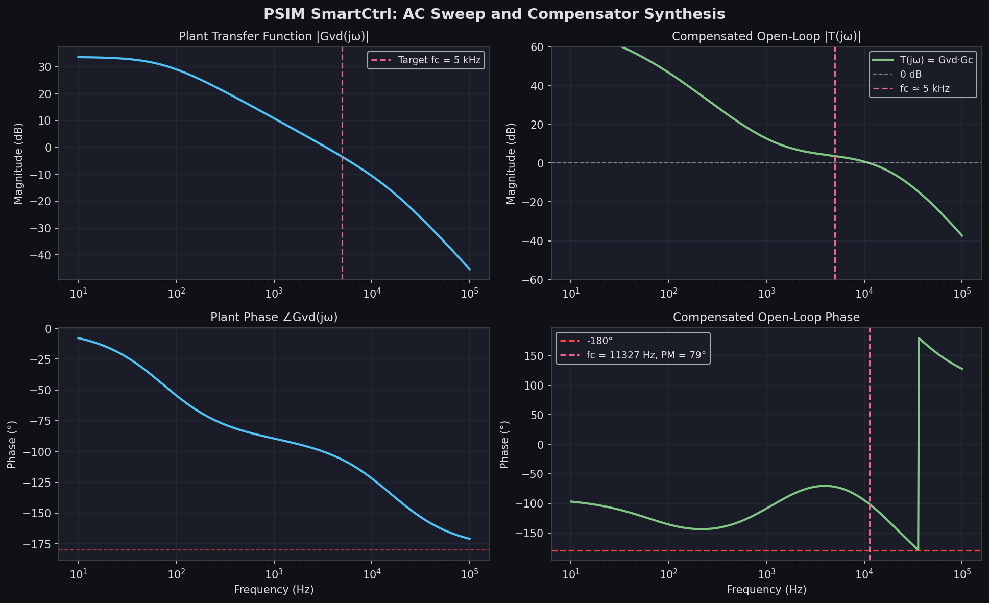
This workflow eliminates the manual iteration between analytical models and simulation that consumes significant engineering time in traditional design flows. Measured crossover frequencies within ±5% of target are routinely achievable on the first SmartCtrl pass for well-characterized topologies.
Thermal Module and Loss Analysis
Accurate loss estimation is critical for heatsink sizing and reliability prediction. PSIM's Thermal Module links device switching and conduction losses to a user-defined thermal network:
- Device loss models are populated from manufacturer datasheet curves (V-I characteristics, switching energy vs. current and voltage). PSIM ships with a library of common IGBTs, MOSFETs, and SiC devices.
- Thermal network: each device is connected to a Foster or Cauer RC ladder representing junction-to-case and case-to-heatsink thermal impedances.
- Transient thermal simulation: junction temperature waveforms are computed alongside electrical waveforms, enabling worst-case thermal stress analysis under load transients.
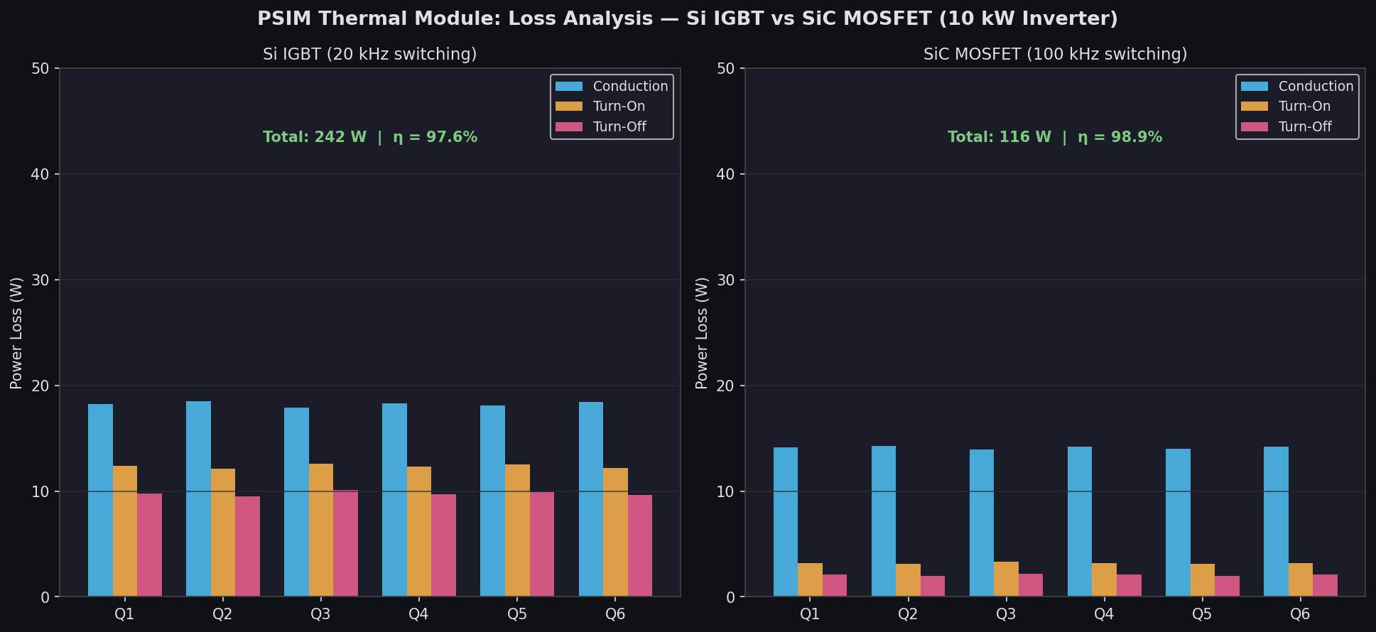
The thermal module output feeds directly into PSIM's loss breakdown report, which itemizes conduction loss, turn-on loss, and turn-off loss per device — essential data for comparing Si IGBT versus SiC MOSFET designs at the same switching frequency.
Co-Simulation with MATLAB/Simulink and SimCoder
For teams that develop control algorithms in Simulink, PSIM offers a SimCoupler interface that runs the PSIM power circuit and the Simulink control model in lock-step. The power circuit state variables are passed to Simulink at each time step, and the Simulink control outputs are returned as gate signals. This allows engineers to leverage Simulink's control design toolboxes while retaining PSIM's fast power circuit solver.
SimCoder takes the workflow further by generating C code directly from a PSIM control schematic, targeting Texas Instruments C2000 DSPs and Microchip dsPIC devices. The generated code includes interrupt service routines, ADC sampling, and PWM peripheral configuration — reducing firmware bring-up time from weeks to days on well-characterized hardware platforms.
Practical Guidance and Limitations
PSIM is best suited for:
- Control-loop design and stability analysis of DC-DC converters, PFC stages, and inverters
- Motor drive development from initial FOC algorithm validation through efficiency mapping
- Rapid loss estimation for thermal design and device selection
It is less appropriate for:
- EMI/EMC analysis requiring accurate parasitic modeling (use SPICE or Q3D Extractor)
- Detailed semiconductor device physics (use Sentaurus or TCAD tools)
- Large-scale grid studies involving hundreds of buses (use PSS/E, PowerFactory, or pandapower)
PSIM's licensing model offers a perpetual base license with optional add-on modules (Motor Drive, Thermal, SimCoder, SmartCtrl), making it cost-effective for teams that need only a subset of capabilities.
Further Resources
- Powersim PSIM Official Documentation
- PSIM Tutorial Library
- SmartCtrl Application Notes
- SimCoder Code Generation Guide
- IEEE PELS Power Electronics Simulation Resources
PSIM occupies a well-defined niche in the power electronics simulation landscape: fast enough for iterative control design, detailed enough for thermal and loss analysis, and tightly integrated with the DSP code generation workflows that define modern converter development. For engineers working on switched-mode power supplies, motor drives, or grid-tied inverters, it deserves a place alongside the general-purpose tools in the simulation toolkit.