
RTDS Technologies RSCAD: Real-Time Digital Simulation for Power System Protection and Control Testing
Real-time digital simulation (RTDS) has become indispensable for validating protection relays, HVDC controls, and inverter-based resource (IBR) controllers before they are deployed on live grids. RTDS Technologies' RSCAD software suite, running on the company's purpose-built NovaCor and PB5 hardware platforms, delivers true electromagnetic-transient (EMT) simulation at time steps as small as 2 µs — fast enough to close the loop with physical hardware in real time. This article examines RSCAD's architecture, its hardware-in-the-loop (HIL) workflow, and best practices for protection relay testing and IBR controller validation.
Why Real-Time EMT Simulation?
Offline EMT tools such as PSCAD and EMTP-RV are excellent for detailed studies, but they cannot interact with physical hardware in real time. When a protection relay or a converter controller must respond to a simulated fault within milliseconds, the simulation must keep pace with wall-clock time. RTDS Technologies pioneered this capability in the early 1990s, and RSCAD remains the dominant platform for:
- Closed-loop relay testing — IEC 61850 GOOSE and sampled-value streams connect directly to physical relays.
- Controller hardware-in-the-loop (CHIL) — Vendor-supplied HVDC or STATCOM controllers are tested against a simulated grid before factory acceptance.
- Power hardware-in-the-loop (PHIL) — A physical power converter is interfaced to the simulator through a power amplifier, enabling full-scale device testing.
- Cyber-security research — Simulated SCADA and IEC 61850 substations allow red-team exercises without risk to live infrastructure.
RSCAD Architecture
Hardware Platforms
RTDS Technologies offers two current hardware generations:
| Platform | Cores per Rack | Minimum Time Step | Typical Network Size |
|---|---|---|---|
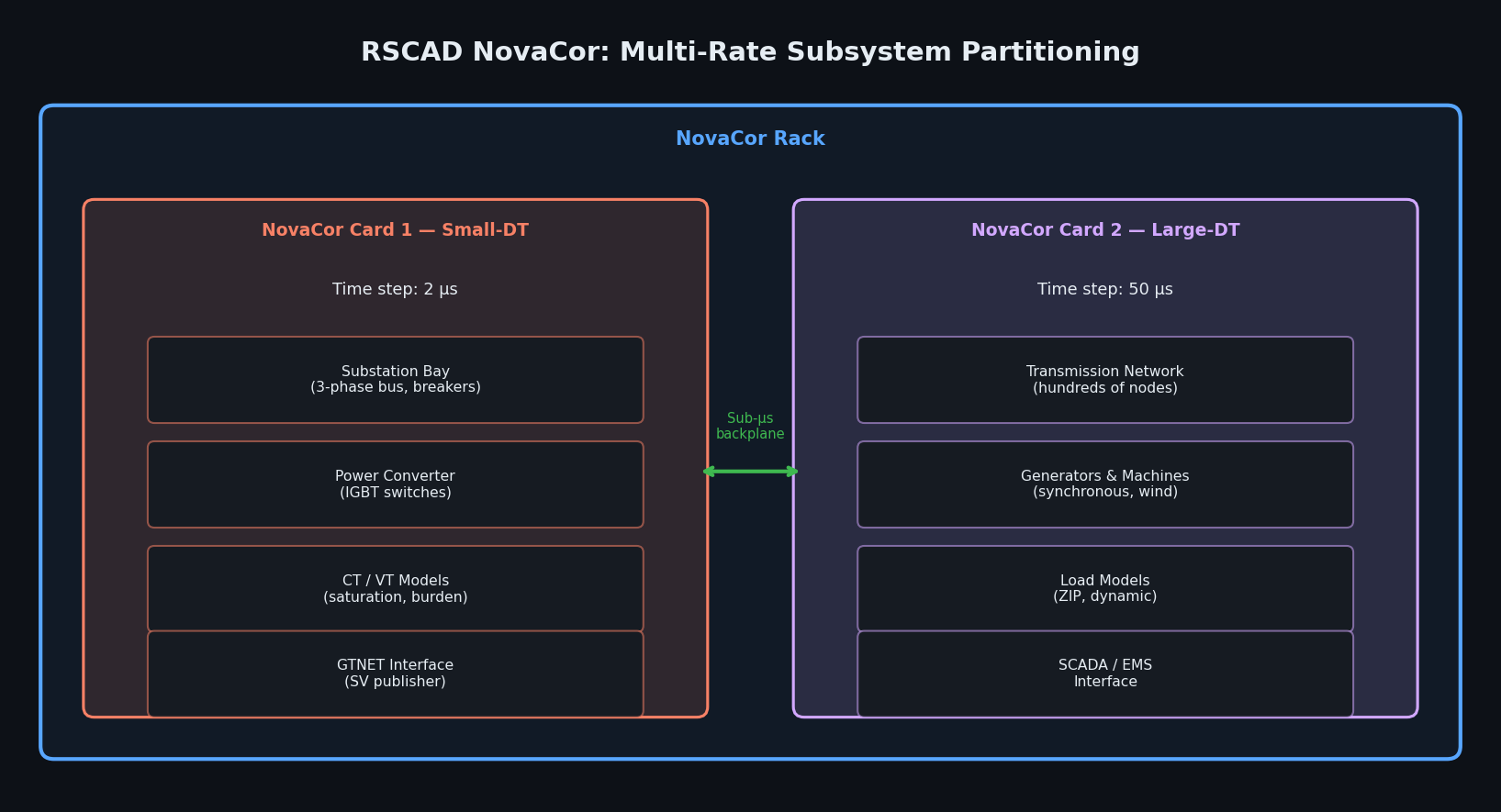
| NovaCor | Up to 12 Intel Xeon cores per card | 2 µs (small-DT) | Hundreds of nodes |
| PB5 (legacy) | DSP-based | 50 µs | Tens of nodes |
NovaCor racks communicate over a low-latency backplane, allowing large networks to be partitioned across multiple cards with sub-microsecond inter-card synchronization.
RSCAD Software Modules
RSCAD is organized into four primary modules:
- Draft — Schematic capture environment where engineers build circuit models from a library of over 400 components (machines, transformers, cables, power electronics, protection elements).
- Runtime — Real-time control panel for starting/stopping simulations, monitoring signals, and injecting faults via sliders and push-buttons.
- TLine (Transmission Line) — Frequency-dependent line parameter calculator that generates Bergeron or wideband line models from tower geometry and conductor data.
- Cable — Underground and submarine cable modeling using frequency-dependent modal decomposition.
A Python scripting interface (rscad_api) introduced in recent releases allows automated test sequences, parameter sweeps, and integration with external test management frameworks.
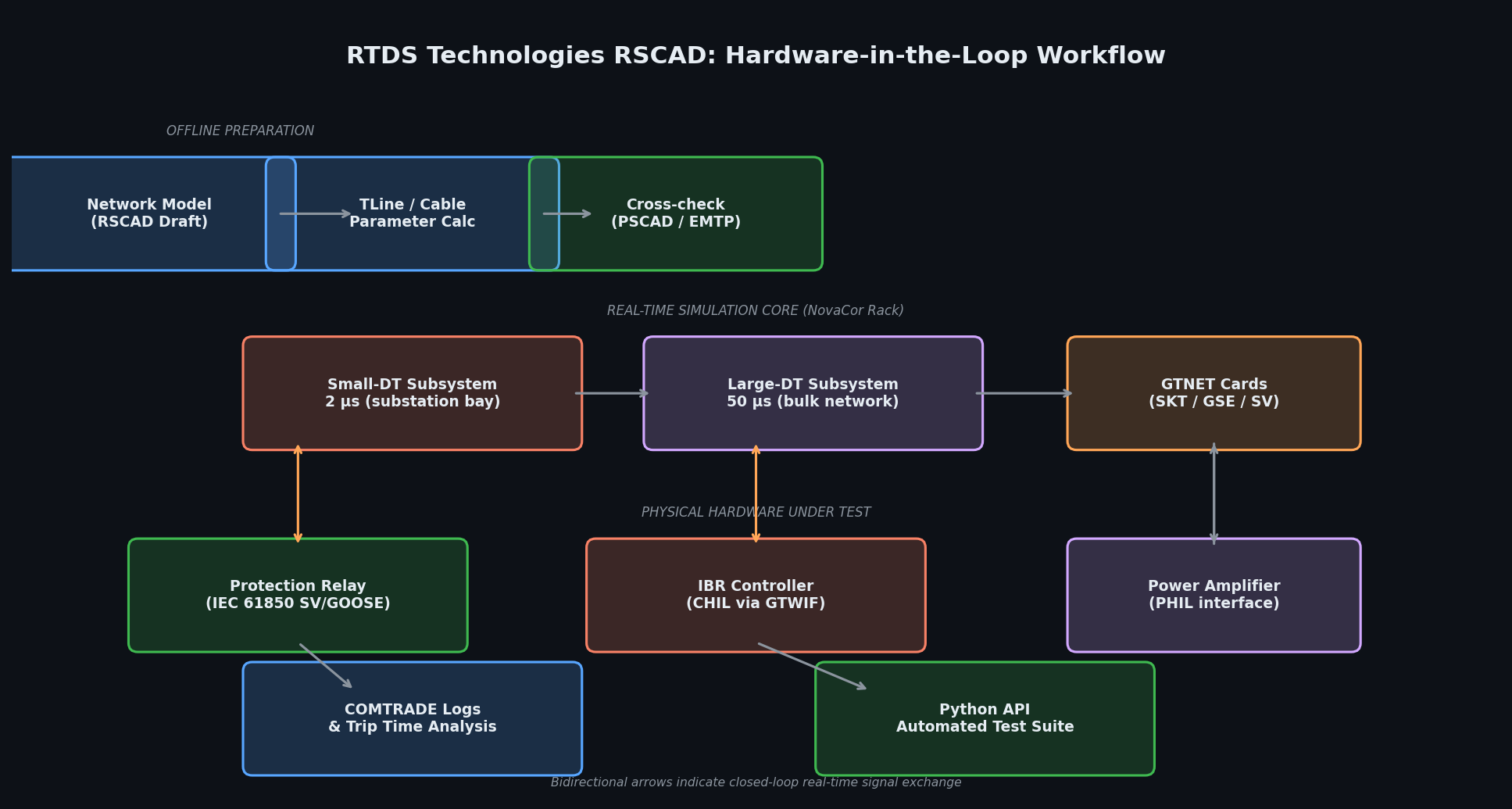
Hardware-in-the-Loop Workflow for Protection Relay Testing
Step 1 — Build the Network Model in Draft
Start with the substation topology: sources, transformers, transmission lines, and loads. Use the GTNET-SKT or GTNET-GSE cards to output analog voltages and currents (via amplifiers) or digital IEC 61850 sampled-value streams directly to the relay under test.
Key modeling decisions:
- Choose the small-DT subsystem (2 µs) for the substation bay containing the relay CT/VT interfaces; the rest of the network can run at 50 µs in a separate subsystem.
- Model CT saturation explicitly if testing high-current differential or distance elements — RSCAD's CT model includes remanence and hysteresis.
- Include the relay's trip output wired back to a GTNET digital input so the simulator can open the breaker in real time.
Step 2 — Configure the GTNET Interface
The GTNET card family provides:
- GTNET-SKT: UDP socket interface for custom protocols and COMTRADE streaming.
- GTNET-GSE: IEC 61850 GOOSE publisher/subscriber.
- GTNET-SV: IEC 61850 sampled-value publisher (up to 80 samples/cycle at 50 Hz).
For modern numerical relays, the sampled-value interface eliminates the need for analog amplifiers, reducing test bench complexity and improving accuracy.
Step 3 — Design the Test Sequence
Use RSCAD Runtime's scripting panel or the Python API to automate:
import rscad_api as rscad
sim = rscad.connect(rack_ip="192.168.1.10")
sim.load_case("substation_model.rscad")
sim.start()
# Apply a phase-A-to-ground fault at 80% of line length
sim.set_parameter("fault_type", 1) # AG fault
sim.set_parameter("fault_location", 0.80)
sim.set_parameter("fault_resistance", 0.0)
sim.apply_fault(duration_ms=100)
# Capture relay trip time
trip_time = sim.wait_for_digital_input(channel=1, timeout_ms=500)
print(f"Relay trip time: {trip_time:.2f} ms")
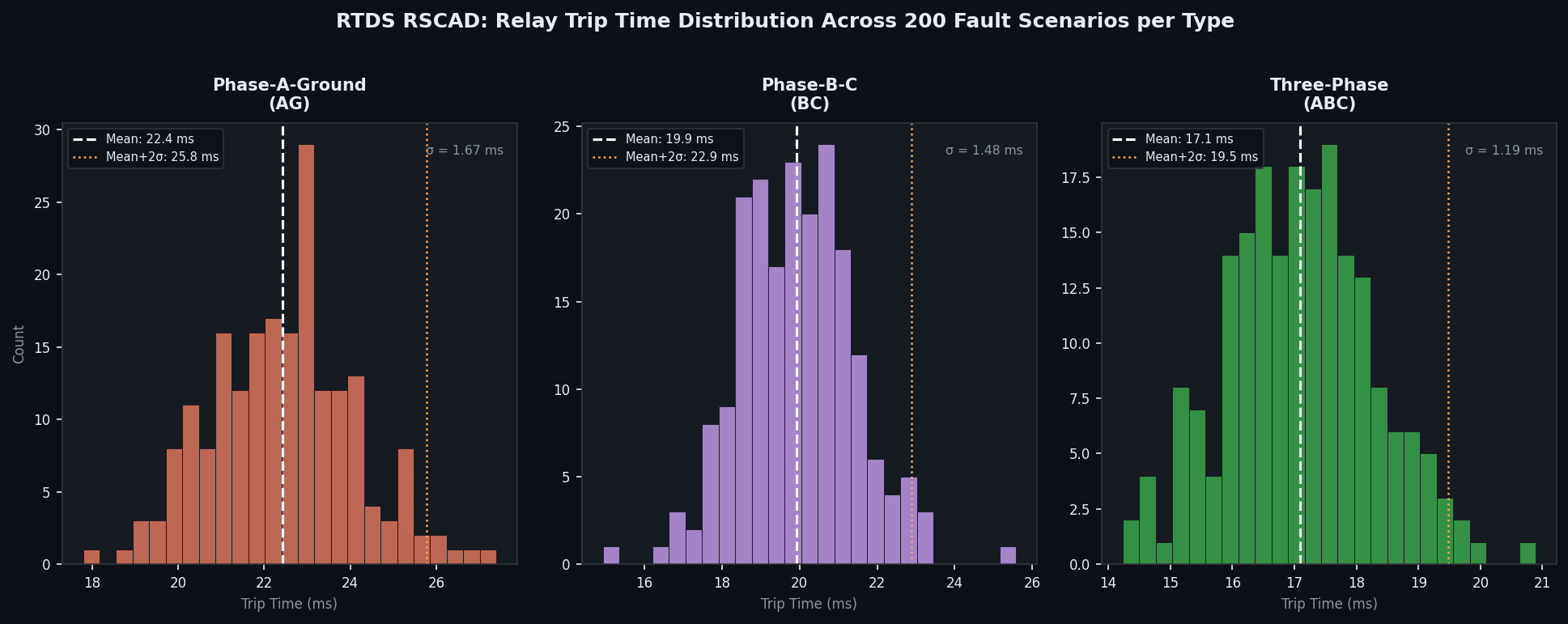
sim.stop()This pattern supports IEC 60255-151 compliance testing across hundreds of fault scenarios without manual intervention.
IBR Controller Validation (CHIL)
Grid-forming and grid-following inverter controllers from wind turbine OEMs and battery storage vendors are increasingly validated using RTDS CHIL before factory acceptance tests. The workflow mirrors relay testing but with higher analog bandwidth requirements:
- Analog I/O: The RTDS GTWIF card provides ±10 V analog outputs at 2 µs update rates, sufficient for most DSP-based controllers.
- Fiber-optic links: Some OEMs use proprietary high-speed fiber interfaces; RTDS supports custom FPGA-based interface cards.
- Frequency-domain validation: Compare the CHIL-measured closed-loop impedance of the IBR against the offline model to confirm the real-time interface introduces no significant phase error.
A common pitfall is interface algorithm instability at the PHIL boundary. RTDS recommends the Ideal Transformer Method (ITM) or Damping Impedance Method (DIM) depending on the Thevenin impedance ratio between the simulated network and the physical device.
Best Practices
- Partition wisely: Place fast-switching power electronics in small-DT subsystems; keep large transmission networks in the 50 µs domain to conserve processor budget.
- Validate offline first: Run the RSCAD model in PSCAD or export to EMTP to cross-check steady-state and transient results before connecting hardware.
- Use COMTRADE logging: RSCAD's built-in COMTRADE recorder captures all analog and digital channels at simulation time step resolution — invaluable for post-test analysis in tools like SIGRA or Python.
- Model the measurement chain: Include CT/VT burden, cable capacitance, and relay input impedance in the model; these affect high-frequency transient fidelity.
- Automate regression testing: Integrate the Python API with CI/CD pipelines so that every firmware update to a relay or controller triggers a full automated test suite.
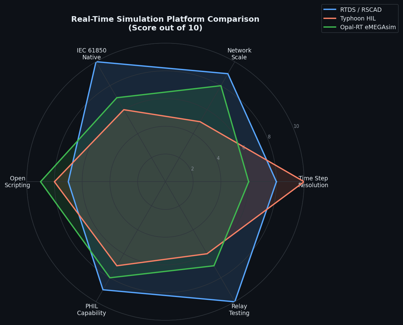
Comparison with Alternative Platforms
| Feature | RTDS / RSCAD | Typhoon HIL | Opal-RT eMEGAsim |
|---|---|---|---|
| Minimum time step | 2 µs | 1 µs | 5 µs |
| Network scale | Very large (multi-rack) | Small–medium | Large |
| IEC 61850 native | Yes (GTNET-GSE/SV) | Via add-on | Via add-on |
| Open scripting | Python API | Python API | MATLAB/Python |
| Primary use case | Utility-scale HIL, relay testing | Power electronics CHIL | Utility + automotive |
Further Resources
- RTDS Technologies Official Documentation
- IEC 62351 Cybersecurity Standards for Power Systems
- IEEE Std 2004-2018: Guide for Specification of Real-Time Digital Simulation Systems
- CIGRE TB 604: Guide for the Application of Real-Time Digital Simulation
- EPRI Real-Time Simulation Handbook
Real-time digital simulation with RTDS RSCAD bridges the gap between offline EMT studies and live grid commissioning. By closing the loop with physical relays and controllers at microsecond time steps, engineers can uncover protection miscoordination, control instabilities, and cyber vulnerabilities that would otherwise only surface during costly field commissioning — or worse, during a grid disturbance.