
Simscape Electrical: Hardware-in-the-Loop Simulation for Power Converter Design and Validation
Power electronics engineers face a persistent challenge: how do you validate a converter control algorithm before committing to expensive hardware prototypes? Simscape Electrical, MathWorks' physics-based electrical simulation library within MATLAB/Simulink, provides a rigorous answer through its Hardware-in-the-Loop (HIL) workflow. By combining high-fidelity switched-mode converter models with real-time target hardware, teams can close the loop between simulation and physical testing months before a PCB is fabricated.
What Is Simscape Electrical?
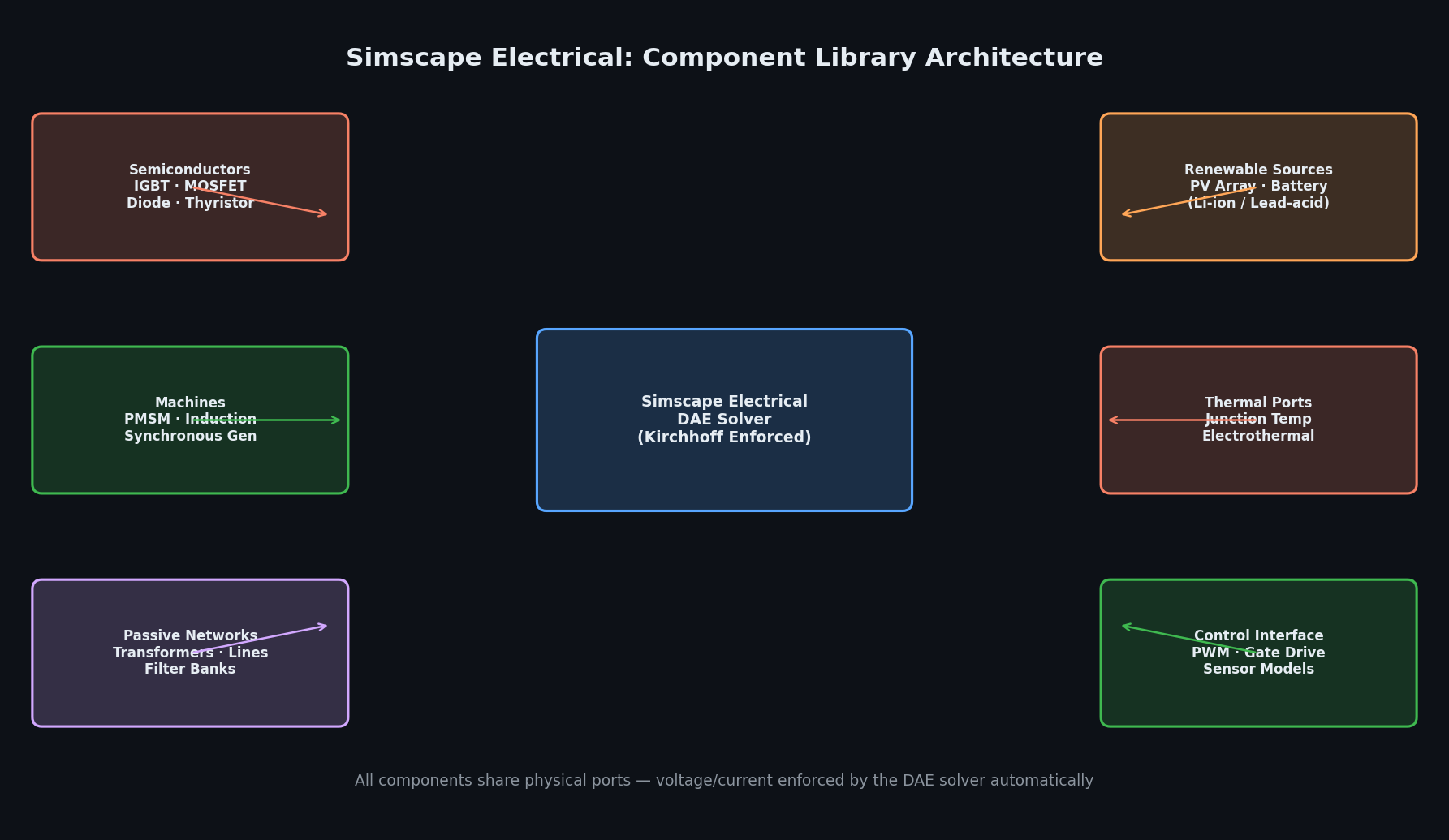
Simscape Electrical (formerly SimPowerSystems and then Simscape Power Systems) is a component library built on the Simscape physical-modeling framework. Unlike signal-flow Simulink blocks, Simscape components represent actual physical quantities — voltage, current, magnetic flux — and enforce Kirchhoff's laws automatically through a differential-algebraic equation (DAE) solver. This means a three-phase voltage-source inverter (VSI) model includes parasitic inductances, dead-time effects, and IGBT switching losses without requiring the engineer to manually wire every node.
Key component families include:
- Semiconductors: IGBT, MOSFET, diode, and thyristor models with thermal ports for junction-temperature tracking
- Machines: Permanent-magnet synchronous motors (PMSM), induction machines, and wound-field synchronous generators with full dq0 dynamics
- Passive networks: Transformers (including saturation and hysteresis), transmission lines (lumped and distributed), and filter banks
- Renewable sources: PV array models with irradiance/temperature dependence and battery models (lithium-ion, lead-acid) with state-of-charge estimation
The HIL Workflow in Practice
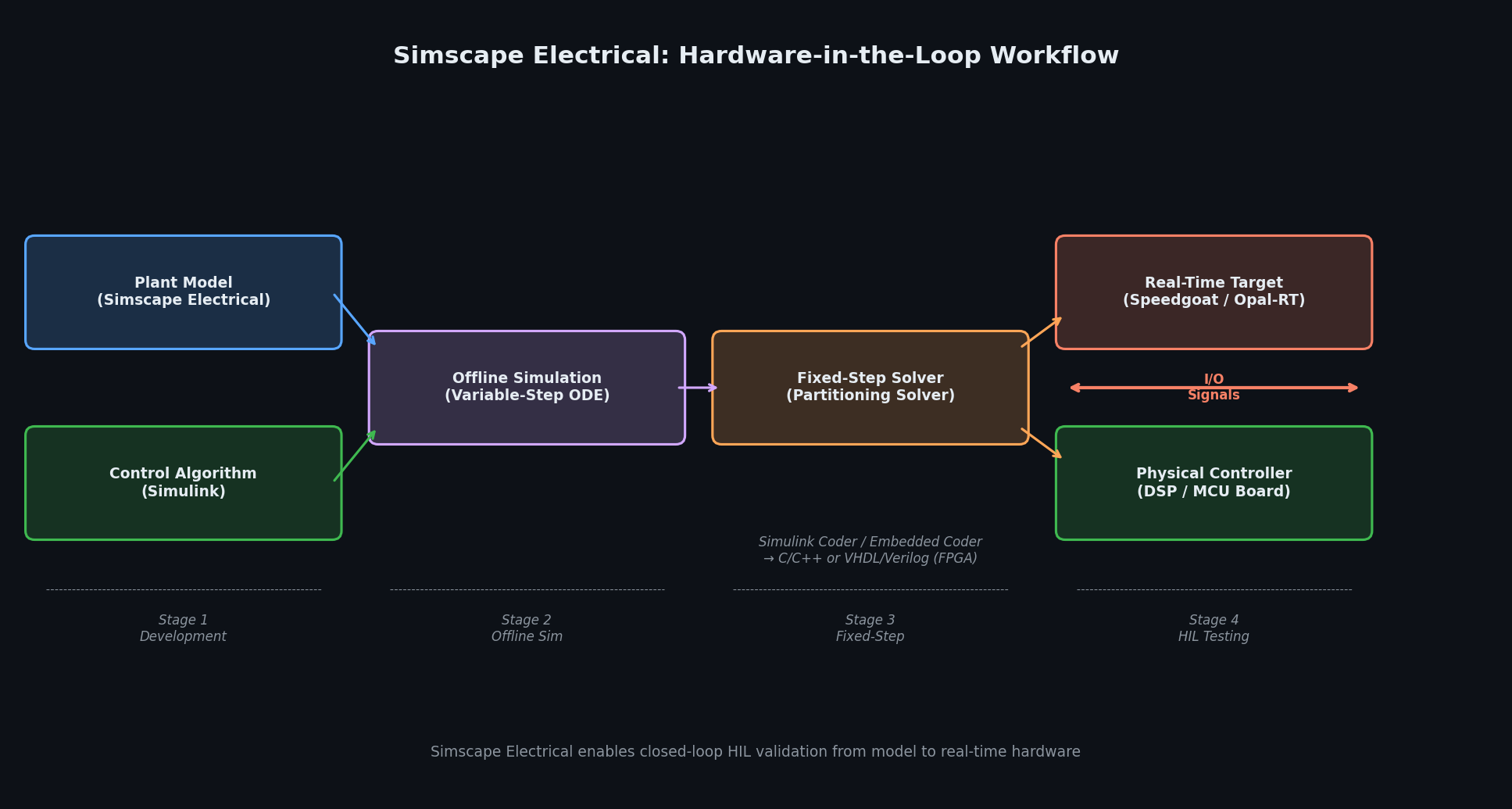
The HIL workflow in Simscape Electrical follows four stages:
1. Model Development and Offline Simulation
Engineers build the plant model (converter + load + grid) in Simscape Electrical and the control algorithm in standard Simulink. The Simscape solver handles stiff switching dynamics using variable-step ODE solvers (ode23t or ode15s are typical choices for power electronics). Offline simulation validates steady-state operating points, transient responses to load steps, and fault ride-through behavior.
2. Fixed-Step Solver Transition
Real-time execution requires a fixed-step solver. Simscape Electrical's Simscape Solver Configuration block exposes a local solver option that decouples the electrical network from the rest of the model, enabling fixed-step simulation without algebraic loops. The Partitioning Solver further accelerates execution by splitting the network into weakly coupled subsystems solved in parallel — critical for multi-converter systems where a single monolithic DAE would be prohibitively slow.
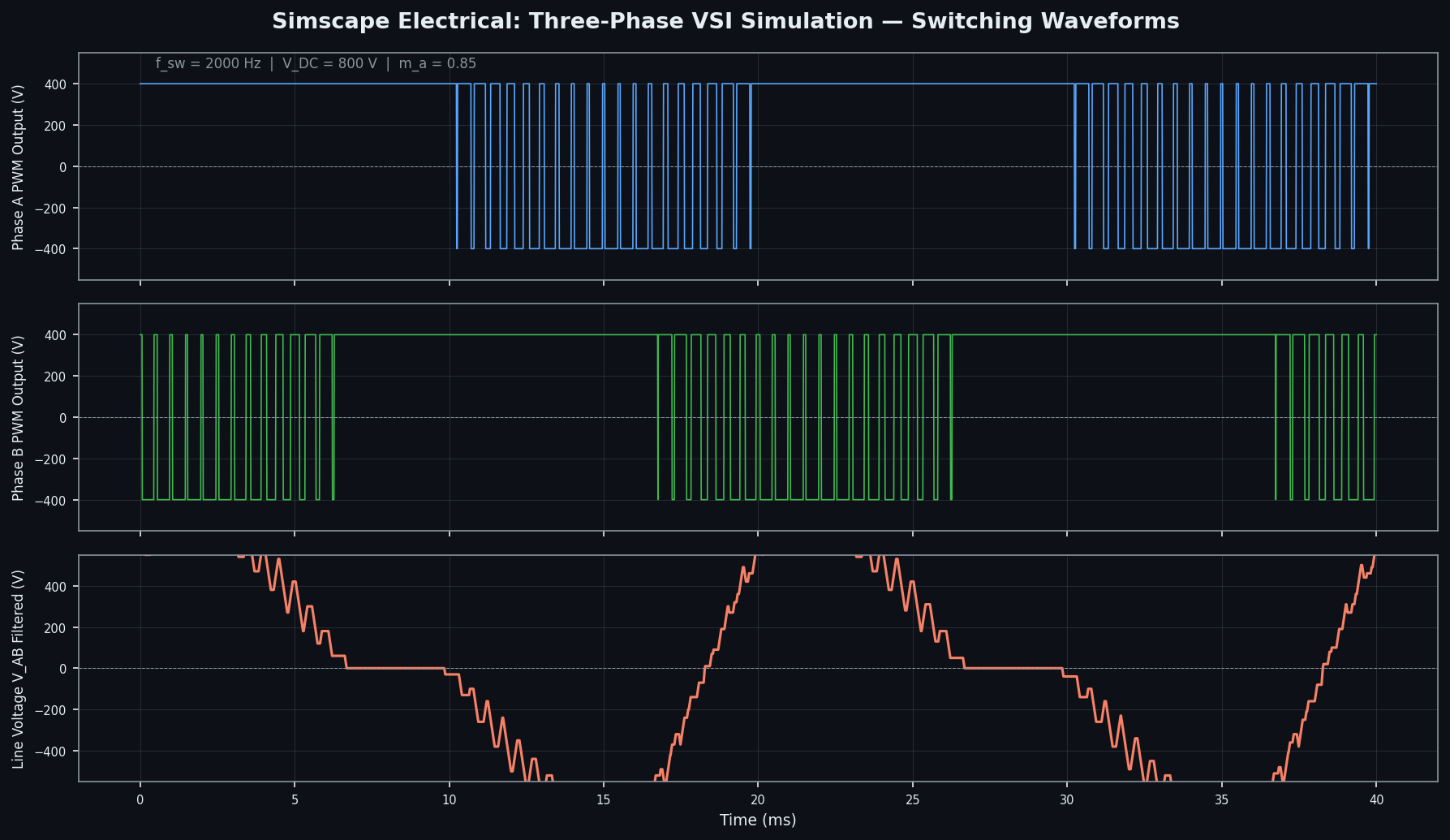
A practical rule of thumb: target a simulation time step of at least 10× smaller than the switching period. For a 20 kHz switching frequency, a 5 µs step is a reasonable starting point; many teams achieve 1–2 µs on modern FPGA-based HIL platforms.
3. Code Generation and Real-Time Deployment
With Simulink Coder and Embedded Coder, the fixed-step model generates C/C++ code that deploys to real-time targets. MathWorks supports Speedgoat real-time machines natively, and third-party HIL platforms (Opal-RT, dSPACE SCALEXIO) accept the generated code via their own toolchains. The Simscape HDL Workflow Advisor can additionally generate synthesizable VHDL/Verilog for FPGA-based ultra-fast HIL, enabling sub-microsecond time steps for SiC/GaN converter validation.
4. Closed-Loop HIL Testing
In the HIL rig, the real-time target runs the plant model while the physical controller under test (a DSP or microcontroller board) receives analog/digital I/O signals representing sensor measurements and drives the model's switching inputs. This closed-loop configuration lets engineers:
- Inject realistic grid disturbances (voltage sags, frequency deviations) and measure controller response
- Stress-test protection logic by simulating short-circuit faults without risk to hardware
- Validate PWM timing and dead-time compensation against the actual gate-driver signals
- Run overnight regression suites covering hundreds of operating points automatically
Practical Guidance: Avoiding Common Pitfalls
Algebraic loops: Simscape Electrical's physical network solver eliminates most algebraic loops internally, but interfacing with signal-based Simulink blocks (e.g., a lookup-table-based MPPT algorithm) can reintroduce them. Use Memory blocks or the PS-Simulink Converter with appropriate filtering to break loops cleanly.
Switching loss accuracy: The default IGBT model uses a simplified on/off resistance. For accurate loss budgets, enable the detailed switching loss model and supply manufacturer datasheet parameters (Eon, Eoff vs. current and temperature). Thermal port connections to a Simscape thermal network then propagate junction temperatures back into the electrical model for electrothermal co-simulation.
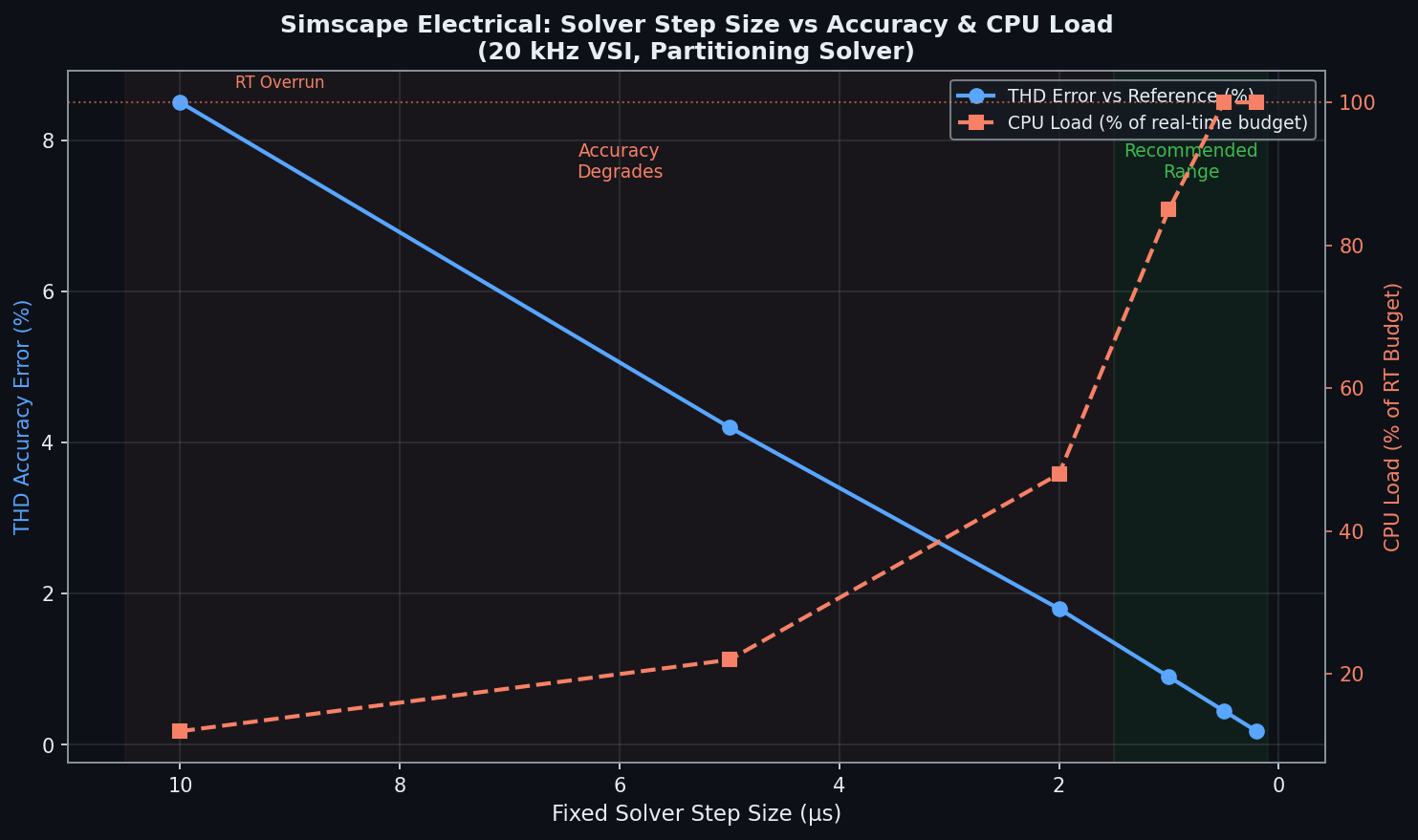
Solver step size vs. accuracy trade-off: Reducing the fixed step improves accuracy but increases CPU load. Profile the model using the Simulink Profiler before deploying to real-time hardware. If the model overruns, consider replacing detailed semiconductor models with averaged models (e.g., the built-in average-value VSI block) for the portions of the circuit not under direct test.
Grid impedance modeling: For grid-connected inverter studies, always include a Thevenin equivalent of the upstream grid with realistic X/R ratio. Omitting grid impedance leads to optimistic stability margins that do not reflect field conditions.
Integration with the Broader MathWorks Ecosystem
Simscape Electrical integrates tightly with:
- Motor Control Blockset: Pre-built FOC and MTPA reference designs for PMSM drives, reducing time-to-HIL for motor drive projects
- Powertrain Blockset: Co-simulation of electric vehicle drivetrains including battery management and thermal systems
- Optimization Toolbox / Global Optimization Toolbox: Automated parameter sweeps for filter design and control tuning
- Simscape Battery: High-fidelity electrochemical battery models (equivalent-circuit and physics-based) for EV and grid storage applications
When to Choose Simscape Electrical
Simscape Electrical is the right tool when:
- The control algorithm is already developed in Simulink and the team wants a single-environment workflow from design through HIL
- Electrothermal co-simulation is required for reliability analysis
- FPGA-based ultra-fast HIL is needed for wide-bandgap (SiC/GaN) converter validation
- Tight integration with Motor Control Blockset or Powertrain Blockset is a project requirement
For large-scale transmission network studies (thousands of buses), dedicated tools like PSS/E or PSCAD remain more appropriate. Simscape Electrical excels at the converter and drive level, where switching dynamics and control interactions are the primary concern.
Further Resources
- MathWorks Simscape Electrical Documentation
- Simscape HDL Workflow Advisor Guide
- Motor Control Blockset Reference Designs
- Speedgoat Real-Time Target Machines
- Opal-RT HIL Solutions for Power Electronics
Simscape Electrical's combination of physics-based fidelity, automated code generation, and seamless HIL deployment makes it one of the most complete environments available for power converter design validation — enabling teams to find control bugs and thermal issues in simulation rather than on the bench.