

ANSYS HFSS for Radar Cross-Section Simulation: Stealth Analysis and Antenna Integration in Defense Platforms

Radar cross-section (RCS) is one of the most consequential electromagnetic signatures in modern defense engineering. Whether designing a low-observable aircraft, a naval vessel, or a guided munition, accurately predicting and minimizing RCS is central to survivability. ANSYS HFSS (High Frequency Structure Simulator) has become the industry-standard full-wave electromagnetic solver for RCS analysis, antenna placement, and radome design across defense and aerospace programs.
What HFSS Solves — and Why Full-Wave Matters
RCS simulation requires solving Maxwell's equations without simplifying assumptions. Unlike physical optics (PO) or geometric theory of diffraction (GTD) approximations — which are fast but break down at low frequencies, near edges, or in complex multi-bounce scenarios — HFSS uses the finite element method (FEM) to compute exact field distributions across arbitrary 3D geometries.
For defense applications, this matters in three specific scenarios:
- Low-frequency resonance regimes — where the target's physical dimensions are comparable to the radar wavelength (e.g., VHF/UHF surveillance radars against small UAVs)
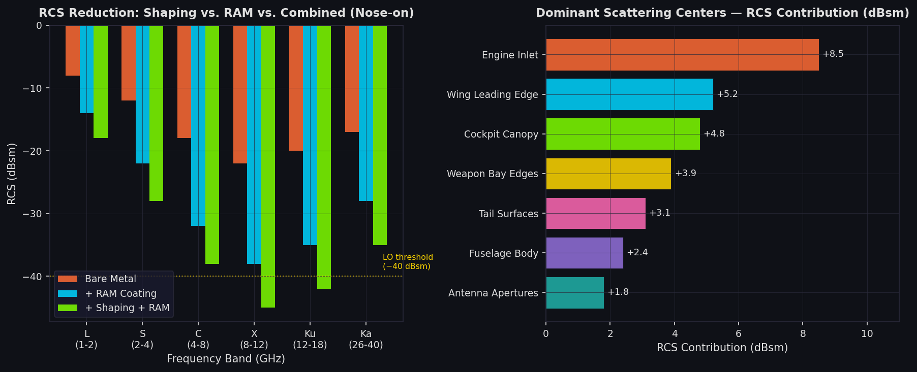
- Complex cavity and inlet geometries — engine inlets, weapon bays, and cockpit cavities produce strong specular and diffraction returns that PO methods underestimate
- Antenna-airframe coupling — conformal antennas embedded in fuselage panels interact with the surrounding structure, creating pattern distortions and unintended RCS contributions
HFSS handles all three with its adaptive mesh refinement, which automatically concentrates mesh density at high-gradient field regions — sharp edges, material interfaces, and apertures — without manual intervention.
RCS Workflow in HFSS
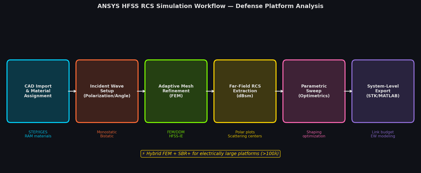
A typical monostatic RCS sweep in HFSS follows this sequence:
1. Geometry Import and Material Assignment
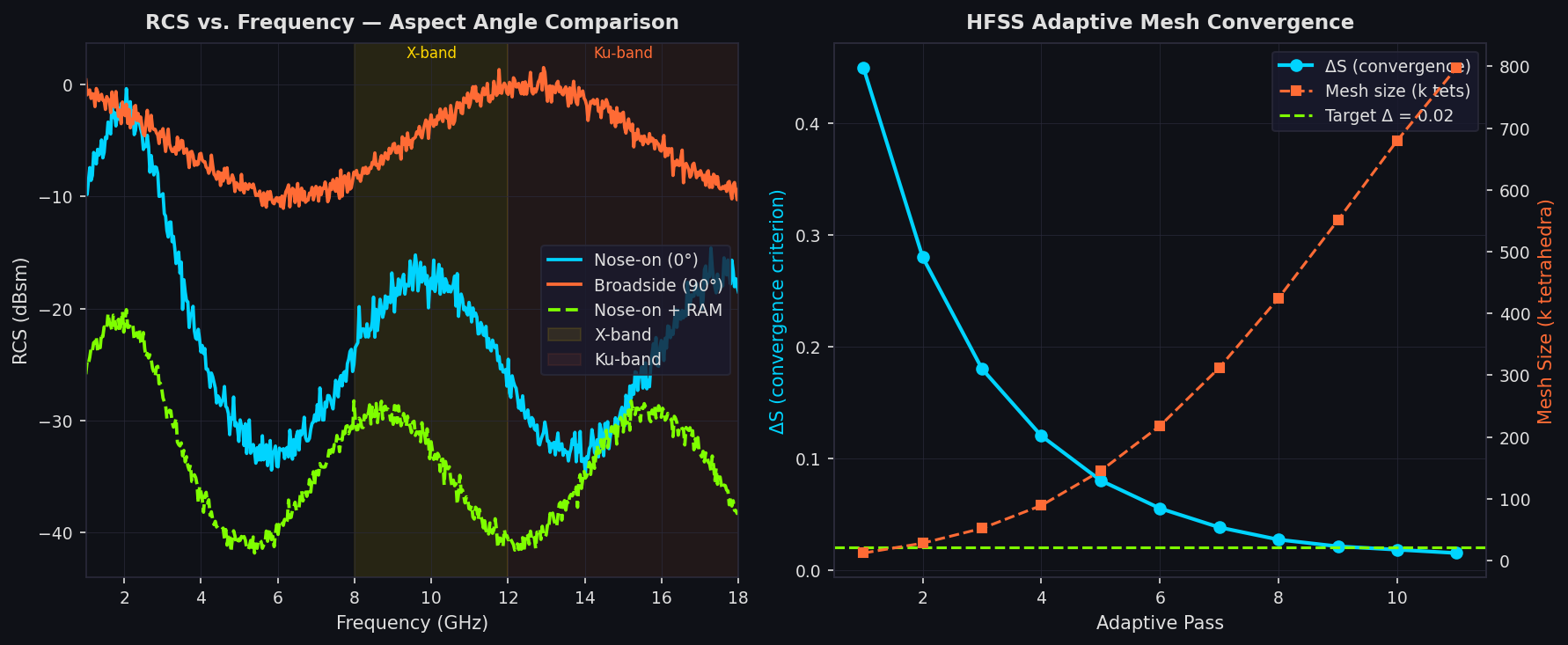
CAD geometry (STEP or IGES) is imported and materials assigned: aluminum alloys, carbon-fiber composites, radar-absorbing materials (RAM), and coatings. HFSS includes a material library with frequency-dependent permittivity and permeability tensors, critical for modeling RAM performance across X-band (8–12 GHz) and Ku-band (12–18 GHz).
2. Incident Wave Setup
A plane wave excitation is defined with specified polarization (HH, VV, or cross-pol) and angle of incidence. For monostatic RCS, HFSS sweeps the incident angle across azimuth and elevation using its Incident Wave Sweep feature, computing the backscattered field at each angle.
3. Adaptive Mesh Refinement
HFSS iteratively refines the tetrahedral mesh until the S-parameter or field solution converges to within a user-specified delta (typically 0.02 or 2%). For electrically large structures — a full-scale fighter at X-band — this can require millions of tetrahedra, making HPC cluster deployment essential.
4. Far-Field RCS Extraction
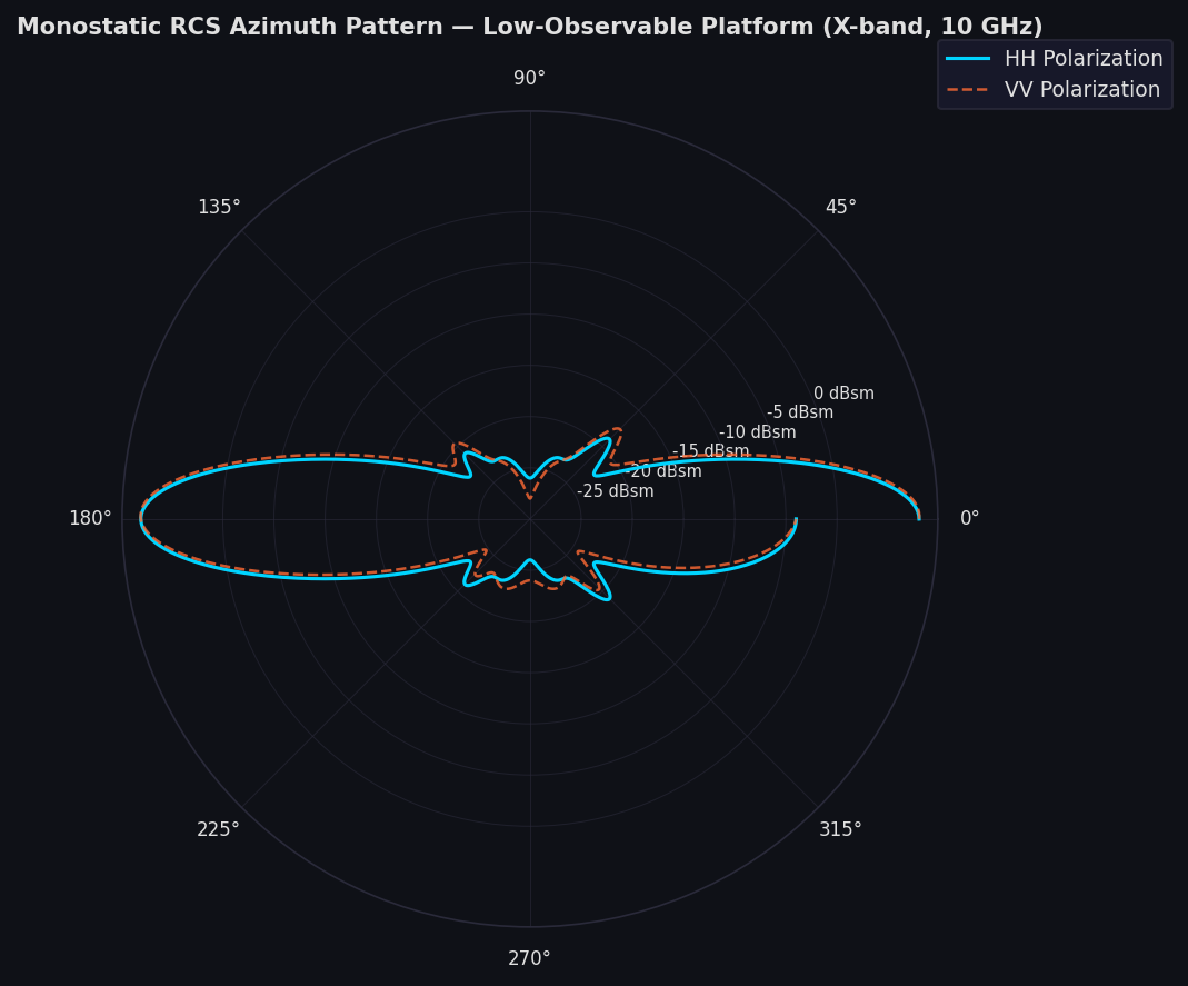
The solver computes the scattered near-field and applies a near-to-far-field transformation to extract RCS in dBsm. Results are visualized as polar plots (RCS vs. azimuth angle) or 3D radiation patterns, enabling engineers to identify dominant scattering centers.
5. Parametric Sweeps for Shaping Studies
HFSS's Optimetrics module enables parametric sweeps over geometry variables — leading-edge sweep angle, inlet lip radius, panel edge serration depth — to quantify their effect on RCS. This is the core workflow for stealth shaping optimization.
Antenna Integration and Installed Performance
Beyond standalone RCS, HFSS is widely used for installed antenna analysis — predicting how an antenna's radiation pattern changes when mounted on a platform. A GPS antenna on a UAV fuselage, for example, will exhibit pattern blockage, multipath, and polarization rotation due to the surrounding structure.
HFSS's Domain Decomposition Method (DDM) partitions electrically large problems across multiple compute nodes, enabling full-platform antenna analysis at operational frequencies. The HFSS-IE (Integral Equation) solver, based on the method of moments (MoM), is particularly efficient for open-region scattering problems where the structure is surrounded by free space — the typical scenario for airborne platforms.
For phased array integration, HFSS computes active element patterns and embedded element patterns that account for mutual coupling between array elements and the airframe. These patterns feed directly into system-level beamforming simulations in MATLAB or STK.
Linking HFSS to System-Level Simulation
HFSS outputs integrate with broader defense simulation workflows:
- STK (Systems Tool Kit): HFSS antenna patterns (exported as .csv or .ffd files) import directly into STK's antenna models for link budget and coverage analysis
- MATLAB Phased Array System Toolbox: Computed element patterns replace idealized isotropic models in radar detection range calculations
- EADSIM: RCS signatures from HFSS parametric sweeps populate threat libraries for electronic warfare scenario modeling
This chain — from full-wave EM simulation to mission-level analysis — is increasingly required in defense acquisition programs, where RCS predictions must be validated against range measurements before platform acceptance.
Practical Considerations
Frequency scaling: Full-wave FEM becomes computationally prohibitive for electrically very large structures (>100λ). For these cases, HFSS can be coupled with ANSYS SBR+ (Shooting and Bouncing Rays), a high-frequency asymptotic solver, in a hybrid workflow that applies FEM to critical sub-regions and SBR+ to the remainder.
Validation: HFSS RCS predictions should be benchmarked against canonical targets (sphere, dihedral, trihedral corner reflector) before applying to classified geometries. ANSYS provides validation datasets for common benchmark cases.
Export control: HFSS models of defense platforms are typically ITAR-controlled. Simulation files, material databases, and RCS results require appropriate handling under export control regulations.