ANSYS Mechanical: Mastering Contact Mechanics for Nonlinear Structural Simulations
Contact mechanics is one of the most computationally demanding and numerically sensitive aspects of finite element analysis (FEA). Whether you are simulating bolted joints, press-fit assemblies, gear tooth engagement, or rubber seals under compression, the accuracy of your results depends critically on how contact interactions are defined and solved. ANSYS Mechanical provides a comprehensive suite of contact formulations and controls that, when properly configured, deliver reliable convergence and physically accurate stress distributions.
Understanding Contact Formulations in ANSYS Mechanical
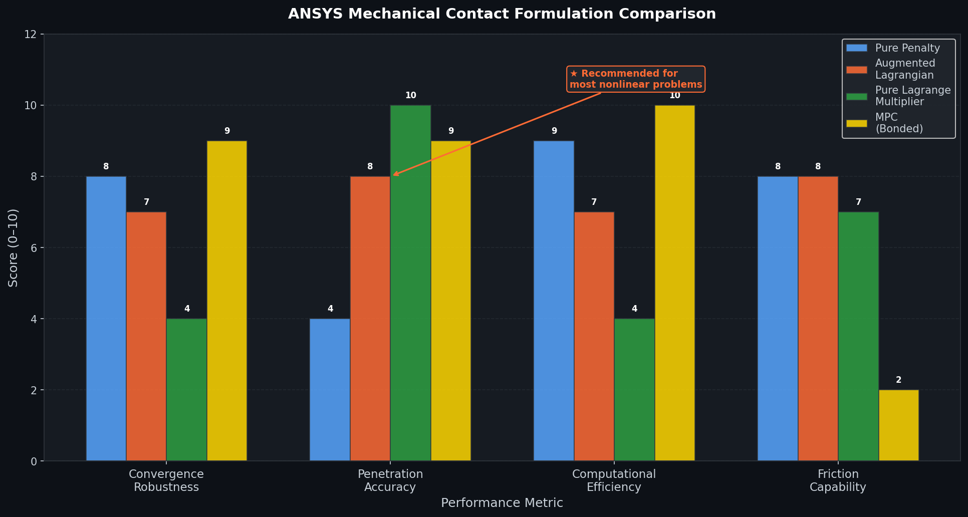
ANSYS Mechanical offers four primary contact formulations, each with distinct trade-offs between accuracy, convergence robustness, and computational cost:
- Pure Penalty Method: The default formulation. Contact forces are applied proportional to penetration depth via a penalty stiffness factor. It is computationally efficient but allows small penetrations that can affect stress accuracy in thin-walled or precision-fit components.
- Augmented Lagrangian (ALG): An iterative enhancement of the penalty method that drives penetration toward zero through successive Lagrange multiplier updates. This is the recommended formulation for most structural contact problems, offering a good balance of accuracy and convergence.
- Lagrange Multiplier (Pure): Enforces zero penetration exactly by introducing additional degrees of freedom. Ideal for problems where penetration must be strictly controlled, such as sealing surfaces, but can cause chattering and convergence difficulties in highly nonlinear scenarios.
- MPC (Multi-Point Constraint): Used for bonded or no-separation contact, this formulation ties nodes algebraically and is computationally the most efficient. It is appropriate for permanently bonded interfaces but cannot model sliding or separation.
For most nonlinear structural analyses involving frictional sliding or intermittent contact, the Augmented Lagrangian formulation is the preferred starting point.

Contact Detection and Normal Stiffness Tuning
The contact detection method determines how ANSYS identifies when surfaces come into contact. The Gauss Point detection method (the default for most formulations) evaluates contact at integration points within each element, providing smooth and accurate force transfer. The Nodal-Normal to Target method is better suited for sharp corners and edge contacts.
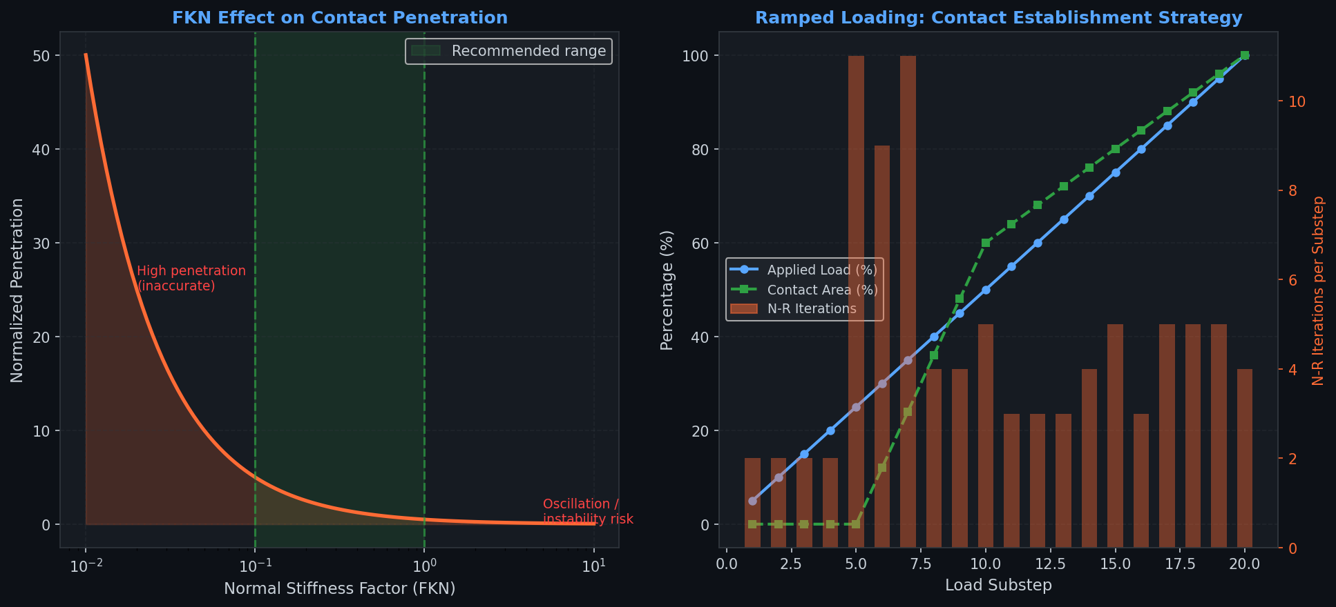
Normal stiffness (the penalty stiffness factor, FKN) is the single most influential parameter for contact convergence. ANSYS automatically calculates a default value based on the underlying material stiffness, but manual tuning is often necessary:
- Reducing FKN (e.g., to 0.1–0.5) improves convergence in highly nonlinear problems at the cost of slightly increased penetration.
- Increasing FKN (e.g., to 1.0–10.0) reduces penetration but can cause numerical instability and oscillation in the contact force.
A practical workflow is to begin with the default stiffness, monitor the Newton-Raphson residual force plots, and reduce FKN if convergence stalls in the contact region.
Friction Modeling: Coulomb vs. Extended Models
ANSYS Mechanical implements the Coulomb friction model as its standard approach, where the tangential contact force is limited by the product of the friction coefficient (μ) and the normal contact pressure. For most metal-on-metal interfaces, μ values between 0.1 and 0.3 are appropriate.
For advanced applications, ANSYS supports:
- Exponential decay friction: Models the transition from static to kinetic friction, important for stick-slip phenomena in precision mechanisms.
- User-defined friction subroutines (USERFRIC): Allows implementation of custom friction laws via APDL scripting, enabling anisotropic friction or velocity-dependent coefficients for tribological studies.
When modeling friction, enabling stabilization damping (via the contact stabilization coefficient) can prevent rigid body motion during the initial load steps before contact is fully established.
Best Practices for Convergence in Nonlinear Contact Problems
Achieving convergence in contact-dominated nonlinear analyses requires a systematic approach:
- Use ramped loading: Apply loads incrementally over multiple substeps rather than in a single step. A minimum of 10–20 substeps for the initial contact establishment phase is recommended.
- Enable automatic time stepping: Set minimum and maximum substep counts (e.g., 10 to 1000) and allow ANSYS to bisect when convergence fails.
- Inspect Newton-Raphson residuals: Use the
NROPTcommand or the Mechanical GUI's convergence plots to identify which contact regions are driving non-convergence. - Pinball radius control: The pinball region defines the zone within which ANSYS searches for contact. Setting it too small misses initial contact; too large causes spurious contact detection. For assemblies with small gaps, set the pinball radius to approximately 2–3× the expected gap size.
- Symmetric vs. asymmetric contact: Symmetric contact (contact on both surfaces) is more accurate but doubles the contact element count. For large models, asymmetric contact with the finer mesh assigned as the contact surface is a practical compromise.
Post-Processing Contact Results
ANSYS Mechanical provides dedicated contact result probes for extracting:
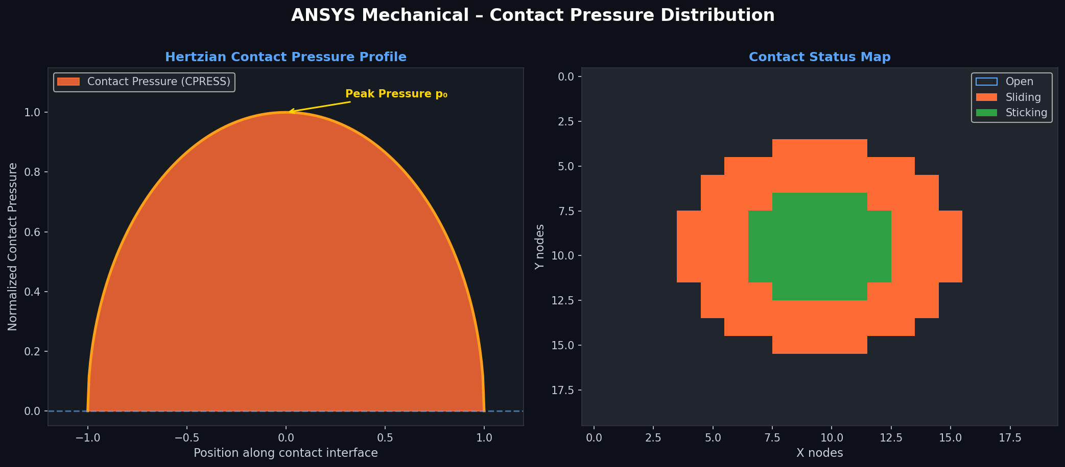
- Contact pressure (CPRESS): The normal stress at the contact interface, critical for wear and fatigue assessments.
- Contact sliding distance (CSLID): Cumulative sliding, used in fretting fatigue and wear calculations.
- Contact status: Identifies regions that are open, sliding, or sticking — essential for validating that the physical contact behavior matches expectations.
- Frictional stress (CFRIC): The tangential stress component, important for joint integrity and bolt preload analyses.
Plotting contact pressure distributions on mating surfaces and comparing them against Hertzian contact theory (for simple geometries) is a recommended validation step before proceeding to full production analyses.
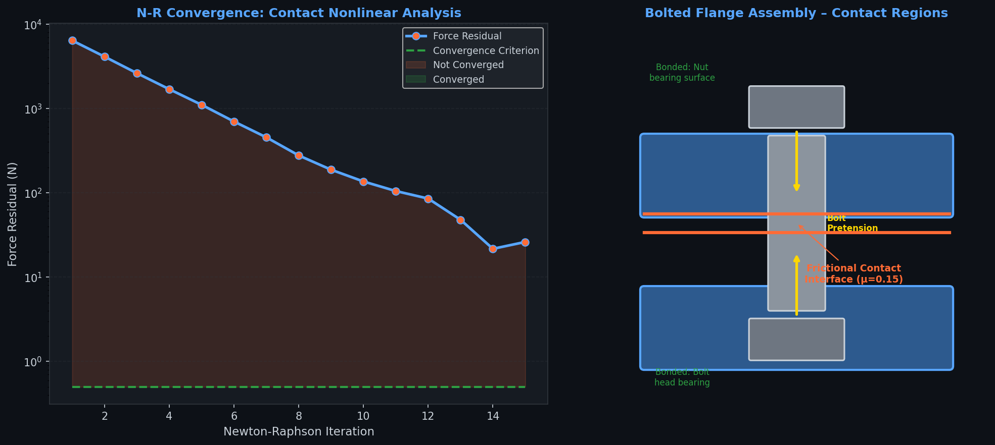
Practical Application: Bolted Flange Assembly
A bolted flange joint illustrates the full workflow. The analysis sequence typically involves:
- Bolt pretension applied via the Bolt Pretension object, which introduces a pre-stress state before external loads are applied.
- Frictional contact between flange faces with μ = 0.15 (steel-on-steel with lubricant).
- Bonded contact between bolt shanks and nut bearing surfaces.
- External pressure load applied to the flange bore to evaluate gasket seating and potential leakage.
This multi-step, multi-contact analysis is a standard validation benchmark for pressure vessel and piping engineers working to ASME Section VIII or EN 13445 standards.
Further Resources
- ANSYS Mechanical Contact Technology Guide — Official documentation covering all contact formulations and APDL commands.
- ANSYS Innovation Courses: Nonlinear FEA — Free structured learning on contact and nonlinear analysis.
- SimScale Contact Mechanics Benchmark — Open validation cases for cross-tool comparison.
- ASME V&V 10-2006 — Standard for verification and validation of computational solid mechanics.
Mastering contact mechanics in ANSYS Mechanical requires iterative experience with formulation selection, stiffness tuning, and convergence diagnostics. The investment pays dividends across virtually every structural simulation domain — from aerospace fastener analysis to biomedical implant design.