
Siemens STAR-CCM+ Overset Mesh: Simulating Moving Bodies in Complex Flow Environments
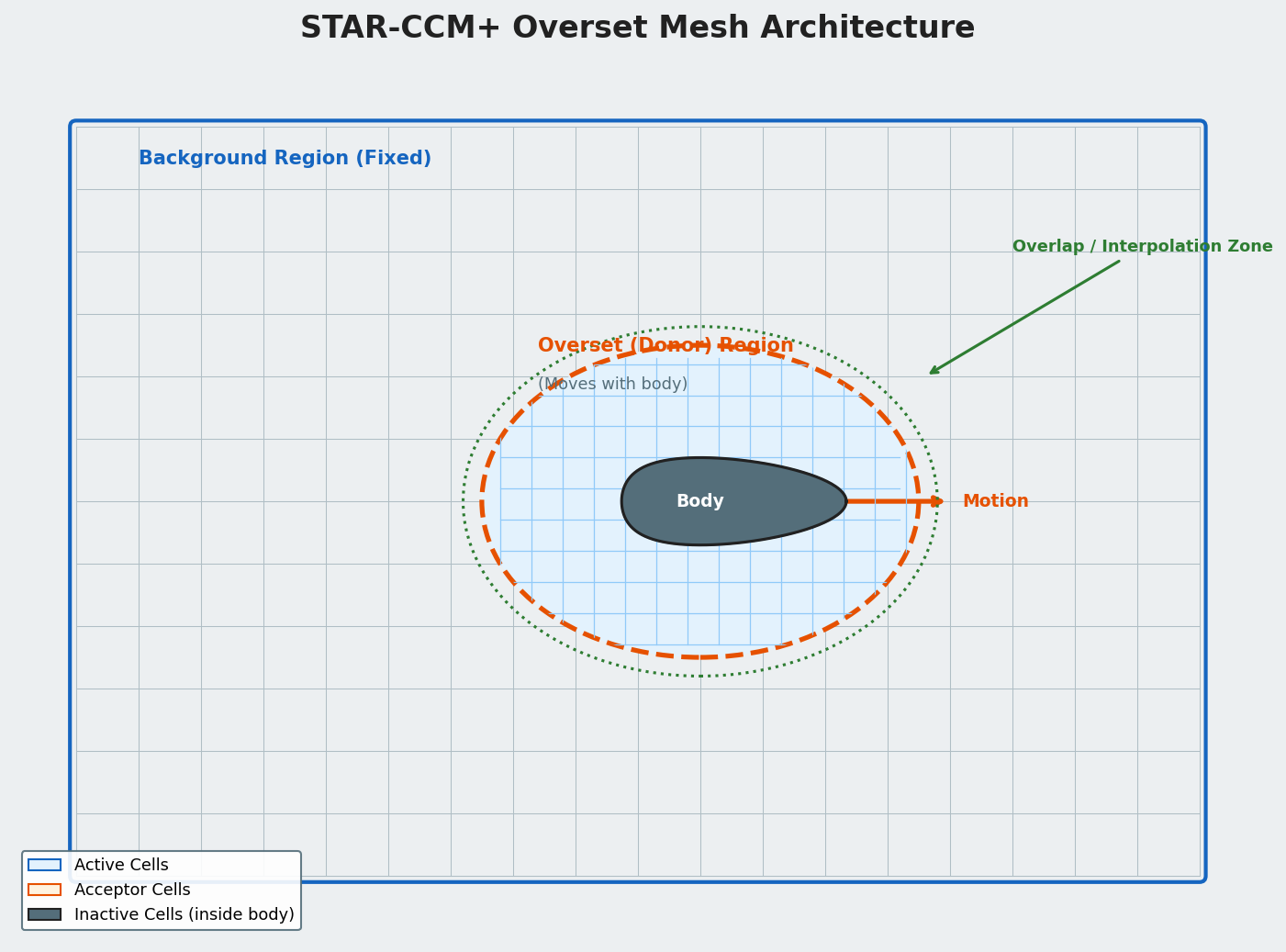
Simulating objects that move through a fluid domain — rotating propellers, deploying control surfaces, store separation from aircraft, or pistons in reciprocating engines — demands a meshing strategy that can accommodate large relative displacements without degrading cell quality. Siemens STAR-CCM+'s Overset Mesh (also called Chimera mesh) capability addresses this challenge by superimposing an independently meshed "donor" region onto a stationary "background" mesh and interpolating solution data across the overlapping zone at every time step. The result is a robust, automation-friendly workflow that avoids the remeshing overhead and quality degradation associated with morphing or sliding-mesh approaches for large-displacement problems.
How Overset Mesh Works in STAR-CCM+
The overset framework maintains two (or more) separate mesh regions:
- Background region — the far-field domain, typically a polyhedral or trimmed-cell mesh that remains fixed throughout the simulation.
- Overset (donor) region — a body-fitted mesh that moves rigidly with the object of interest. It is embedded inside the background mesh.
At each time step, STAR-CCM+ identifies active, inactive, and acceptor cells through an automatic hole-cutting algorithm. Acceptor cells lie at the boundary between the two meshes and receive interpolated values from donor cells in the overlapping region. The interpolation uses a least-squares scheme that is second-order accurate in space, preserving the overall solver accuracy.

The motion of the overset region is prescribed via STAR-CCM+'s Motion framework, which supports:
- Prescribed rigid-body motion — sinusoidal, tabular, or user-defined field functions for position and orientation.
- DFBI (Dynamic Fluid-Body Interaction) — six-degree-of-freedom equations of motion solved in-loop with the CFD solver, enabling free-flight, store separation, and wave-induced ship motion studies.
- Morphing + Overset hybrid — small elastic deformations handled by mesh morphing within the overset region while large translations use the overset framework.
Setting Up an Overset Simulation
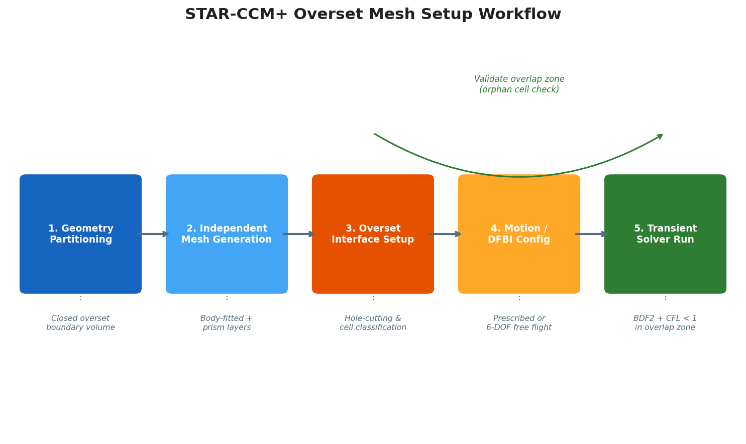
1. Geometry and Region Preparation
Create a closed volume around the moving body that will become the overset region. This volume must extend far enough from the body surface that the overlap zone contains at least 4–6 cell layers on both the background and overset sides — the minimum required for stable interpolation. A common rule of thumb is to size the overset boundary at 3–5 body diameters from the surface.
In the STAR-CCM+ scene, assign the body-enclosing volume to an Overset Mesh region type and the surrounding domain to a Background region type. Link them with an Overset Mesh Interface under the Interfaces node.
2. Mesh Generation
Mesh each region independently:
- Background mesh: Use a trimmed-cell or polyhedral mesher with volumetric refinement in the expected trajectory corridor. Avoid abrupt cell-size transitions near the overlap zone.
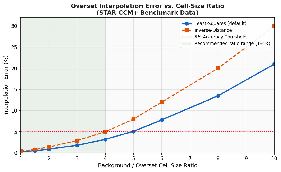
- Overset mesh: Generate a body-fitted surface mesh and apply prism layers for boundary-layer resolution. The cell size at the overset boundary should be within a factor of 2–4 of the background cell size at the same location to minimize interpolation error.
STAR-CCM+'s Automated Mesh Pipeline can generate both meshes in a single operation when the geometry is properly partitioned, significantly reducing setup time.
3. Solver and Time-Step Selection
Overset simulations are inherently transient. Key settings:
| Parameter | Recommended Practice |
|---|---|
| Time-step size | CFL < 1 in the overlap zone; typically Δt = 0.001–0.01 s for subsonic cases |
| Inner iterations | 5–15 per time step for segregated (SIMPLE) solver |
| Interpolation scheme | Least-squares (default); switch to inverse-distance for highly skewed overlap zones |
| Hole-cutting frequency | Every time step for DFBI; every N steps for prescribed motion if geometry is simple |
Enable Second-Order Temporal Discretization (BDF2) for accurate transient resolution. For DFBI cases, activate the Predictor-Corrector coupling option to stabilize the fluid-structure interaction loop.
4. Validating the Overlap Zone
Before running the full transient, perform a static check at the initial position:
- Run 50–100 steady-state iterations with the overset region fixed.
- Inspect the Overset Cell Status scalar scene — all cells should be classified as Active, Inactive, or Acceptor with no "orphan" cells (cells that cannot find a valid donor).
- Check the Interpolation Error report; values above 5% indicate insufficient overlap or excessive cell-size ratio.
Orphan cells are the most common failure mode and typically arise when the overset boundary passes too close to a wall boundary in the background mesh or when the overlap zone is too thin.
Practical Application: Store Separation from a Wing
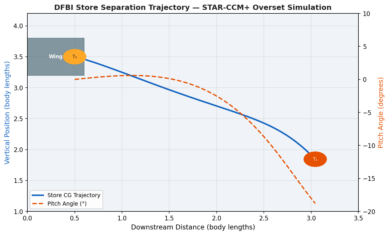
A representative use case is simulating a munition or external fuel tank separating from an aircraft wing under aerodynamic and gravitational loads. The workflow:
- Background mesh: Full aircraft geometry (or half-model with symmetry plane) at cruise conditions.
- Overset region: Store body with its own boundary-layer mesh, initialized at the pylon attachment point.
- DFBI motion: Six-DOF equations integrate aerodynamic forces and moments from the CFD solution plus gravity to advance the store position each time step.
- Output: Time-history of store trajectory, pitch/yaw angles, and aerodynamic coefficients — critical data for safe separation envelope certification.
This approach has been validated against wind-tunnel captive-trajectory system (CTS) data and shows good agreement (within 3–5% on trajectory) when the background mesh is sufficiently refined in the separation corridor.
Performance Considerations
Overset simulations carry a computational overhead compared to single-mesh approaches:
- Hole-cutting adds ~5–15% wall-clock time per time step, depending on mesh complexity.
- Parallel scalability is slightly reduced because the hole-cutting algorithm requires global cell-status communication. STAR-CCM+ mitigates this with a localized search algorithm introduced in v2310.
- For GPU acceleration (via the STAR-CCM+ GPU solver), overset is fully supported on NVIDIA A100/H100 hardware, delivering 3–8× speedup over CPU-only runs for meshes above 20 million cells.
Key Limitations and Workarounds
| Limitation | Workaround |
|---|---|
| Orphan cells near tight clearances | Increase overlap zone thickness; refine background mesh locally |
| Accuracy loss at high cell-size ratios | Add intermediate refinement zones in background mesh |
| Increased memory footprint | Use parallel partitioning with METIS to balance load |
| Convergence stall in DFBI | Reduce time-step size; increase inner iterations; use under-relaxation on body forces |
Further Resources
- Siemens STAR-CCM+ Overset Mesh Documentation — official reference covering all overset settings and field functions.
- STAR-CCM+ User Community (Siemens Support Center) — forums, tutorials, and best-practice guides from Siemens engineers.
- Noack, R.W. (2005). CHIMPS: A CFD Solution Algorithm for Overset Grids. AIAA Paper 2005-5117 — foundational theory behind Chimera interpolation methods.
- NASA CFD Vision 2030 Study — context for where overset methods fit in the broader CFD roadmap.
Overset mesh in STAR-CCM+ is a mature, production-ready capability that dramatically expands the class of moving-body problems accessible to CFD engineers. With careful attention to overlap zone sizing, cell-size ratios, and time-step selection, it delivers accurate, automation-friendly simulations that would be impractical with traditional remeshing approaches.