
Cadence Spectre RF: Harmonic Balance Analysis for Nonlinear RF Circuit Design
Modern RF and microwave circuit design demands accurate simulation of nonlinear behavior under large-signal conditions. While traditional SPICE-based transient analysis can handle these scenarios, it becomes computationally prohibitive for high-frequency circuits operating in the gigahertz range. Cadence Spectre RF's Harmonic Balance (HB) analysis offers a powerful alternative, enabling engineers to efficiently characterize mixer performance, amplifier compression, and intermodulation distortion in RF systems.
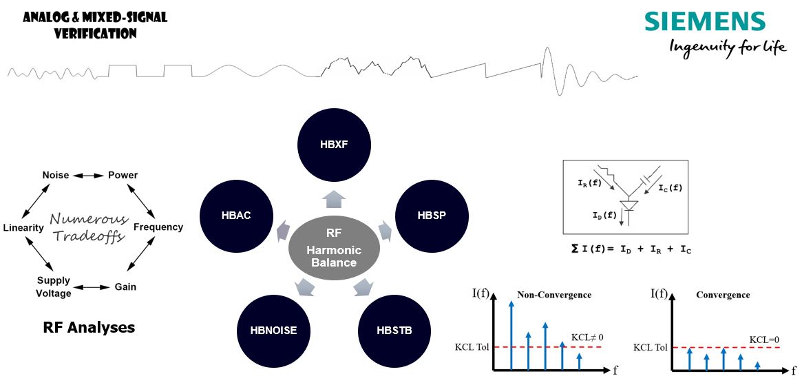
Figure 1: Harmonic Balance analysis workflow showing frequency-domain and time-domain transformations
Understanding Harmonic Balance Fundamentals
Harmonic Balance is a frequency-domain technique that solves for the steady-state response of nonlinear circuits driven by one or more sinusoidal sources. Unlike transient analysis, which marches through time until steady-state is reached, HB directly computes the periodic steady-state solution by representing signals as a sum of harmonics. This approach reduces simulation time by orders of magnitude for RF circuits, where reaching steady-state through transient analysis might require thousands of RF cycles.

The method works by partitioning the circuit into linear and nonlinear subcircuits. Linear elements are analyzed in the frequency domain using their impedance representations, while nonlinear devices are evaluated in the time domain. An iterative algorithm alternates between frequency and time domains using Fast Fourier Transforms (FFT) until the solution converges to satisfy Kirchhoff's laws in both domains simultaneously.
Configuring Harmonic Balance Simulations
Effective HB analysis requires careful setup of several critical parameters. The fundamental frequency (or frequencies for multi-tone analysis) must be specified along with the maximum harmonic order to retain. For a single-tone analysis of a power amplifier at 2.4 GHz, retaining 7-9 harmonics typically provides sufficient accuracy to capture third-order intermodulation products and compression behavior.
Multi-tone HB analysis extends this capability to scenarios involving multiple input frequencies, such as mixer circuits or amplifiers with two-tone excitation for intermodulation testing. When analyzing a mixer with a 1.9 GHz RF input and 2.1 GHz local oscillator, Spectre RF automatically generates mixing products at all significant intermodulation frequencies, allowing direct observation of conversion gain, image rejection, and spurious responses.
Convergence settings significantly impact both accuracy and simulation time. The errpreset parameter offers predefined accuracy levels (liberal, moderate, conservative), while advanced users can fine-tune individual tolerances for voltage, current, and charge conservation. For circuits with strong nonlinearities like switching mixers, tighter tolerances and increased maximum iterations may be necessary to achieve convergence.
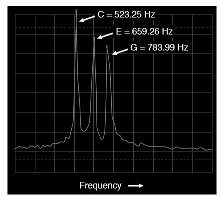
Figure 2: Spectrum analyzer display showing fundamental frequency and harmonic components
Advanced Analysis Capabilities
Spectre RF extends basic HB analysis with several specialized techniques. Harmonic Balance with Shooting combines HB with time-domain shooting methods to handle circuits with both fast RF oscillations and slow envelope variations, such as power amplifiers with bias modulation. This hybrid approach maintains the efficiency of HB for the carrier while accurately capturing envelope dynamics.
Envelope Following analysis takes this further by treating the RF carrier as a fast time scale and the modulation envelope as a slow time scale. This proves invaluable for simulating digitally modulated signals like OFDM or QAM, where traditional HB would require an impractical number of harmonics to represent the complex modulation spectrum. Engineers can directly apply modulated waveforms and observe spectral regrowth, adjacent channel power ratio (ACPR), and error vector magnitude (EVM) with realistic signal statistics.
Periodic Steady-State (PSS) analysis, while technically distinct from HB, complements it by finding the periodic steady-state of autonomous circuits like oscillators. Once PSS establishes the oscillation frequency and waveform, subsequent analyses like Periodic AC (PAC) and Periodic Noise (PNoise) can characterize oscillator phase noise, pulling, and injection locking behavior.

Figure 3: Ideal mixer circuit showing frequency conversion and intermodulation products
Practical Workflow and Best Practices
A typical RF design workflow begins with DC operating point analysis to verify bias conditions, followed by small-signal S-parameter extraction to validate matching networks and stability. HB analysis then characterizes large-signal performance: 1-dB compression point, third-order intercept point (IP3), and harmonic content. For mixer designs, conversion gain and port-to-port isolation are extracted directly from multi-tone HB results.
Post-processing capabilities in Spectre RF's calculator environment enable sophisticated measurements. Built-in functions compute power spectral density, total harmonic distortion (THD), and intermodulation ratios directly from HB results. Custom expressions can extract specific mixing products or calculate figures of merit like noise figure under large-signal conditions using the PNoise analysis.
Model accuracy remains paramount. While ideal transmission lines and lumped elements suffice for initial exploration, production-level simulations demand electromagnetic-extracted S-parameter models for passive structures, foundry-provided nonlinear models for active devices, and realistic package parasitics. Spectre RF seamlessly integrates these diverse model types within a unified simulation framework.
Integration with Design Flows
Spectre RF operates within the Cadence Virtuoso environment, enabling tight integration with schematic capture, layout, and electromagnetic simulation. Parametric sweeps across bias conditions, input power, or component values can be automated using the Analog Design Environment (ADE). Results feed directly into optimization loops or corner analysis to ensure robust performance across process, voltage, and temperature (PVT) variations.
For system-level verification, Spectre RF co-simulates with Virtuoso System Design Platform, allowing RF front-ends designed in Spectre to interface with digital baseband models in Verilog or SystemVerilog. This mixed-signal capability proves essential for verifying transceiver architectures where RF performance impacts digital demodulation quality.
Conclusion
Cadence Spectre RF's Harmonic Balance analysis represents a mature, production-proven approach to nonlinear RF circuit simulation. By operating in the frequency domain and exploiting the periodic nature of RF signals, it delivers the speed necessary for iterative design while maintaining the accuracy required for first-pass silicon success. Mastery of HB analysis techniques, from basic single-tone characterization to advanced envelope simulation, empowers RF engineers to tackle increasingly complex wireless communication systems with confidence.
For engineers seeking to deepen their expertise, Cadence provides comprehensive documentation through the Spectre RF User Guide and application notes covering specific circuit topologies. Academic resources on harmonic balance theory, such as those from IEEE Microwave Theory and Techniques Society, offer mathematical foundations for understanding convergence behavior and accuracy trade-offs.