
InfraWorks + Civil 3D + InfoDrainage: A Three-Stage Workflow for Urban Drainage Simulation
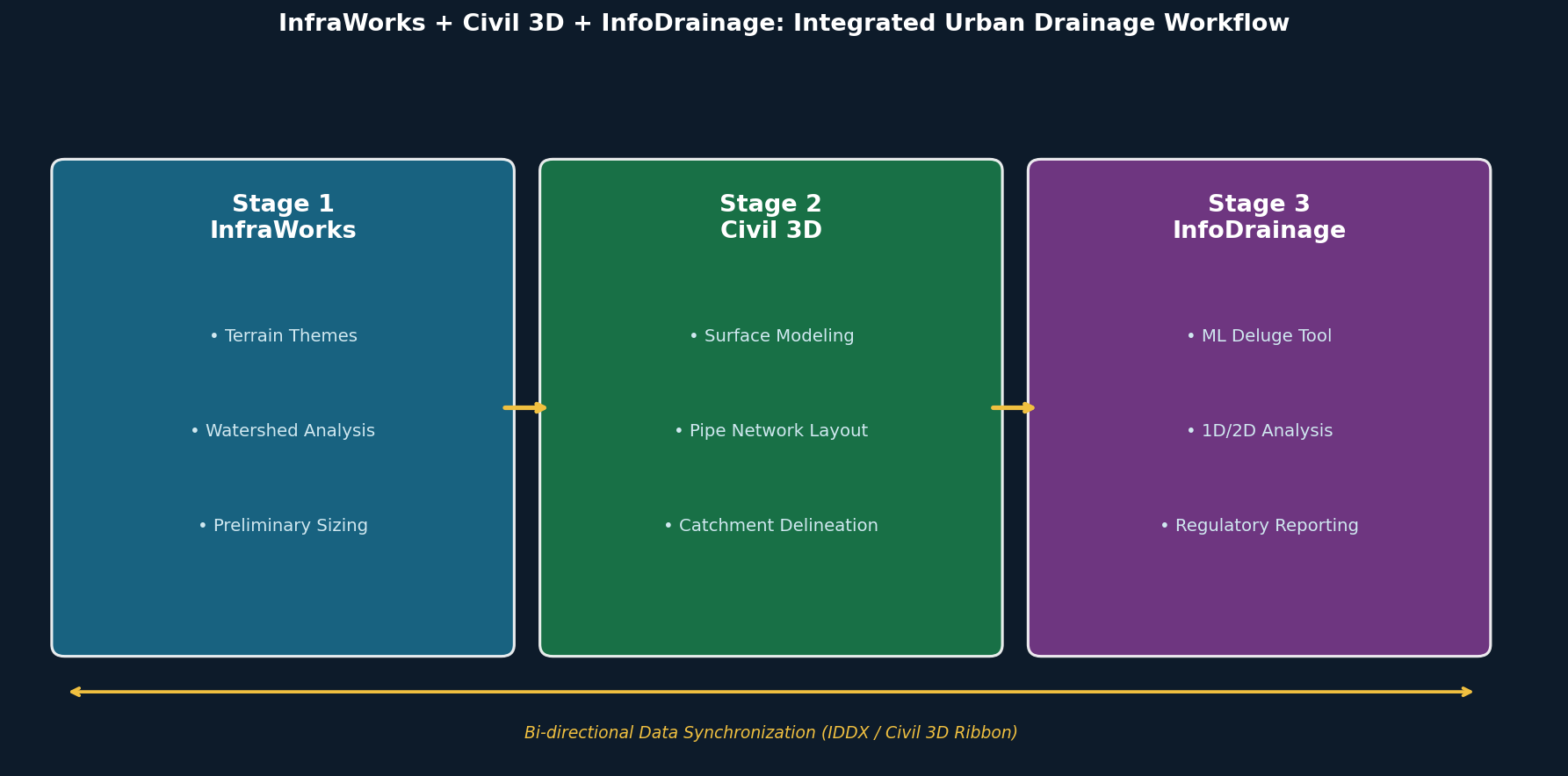
Urban drainage design has historically been fragmented across disconnected tools, forcing engineers to manually re-enter data between conceptual planning, network layout, and hydraulic analysis phases. Autodesk's integrated workflow—spanning InfraWorks, Civil 3D, and InfoDrainage—addresses this by creating a continuous, bi-directional data pipeline from preliminary site assessment through regulatory-grade hydraulic simulation. For infrastructure engineers working on urban stormwater systems, understanding how to leverage each tool's strengths within this workflow is essential for producing accurate, defensible designs.
Stage 1: Watershed Reconnaissance in InfraWorks
InfraWorks serves as the entry point for drainage projects, aggregating GIS data, aerial imagery, terrain models, and existing utility records into a georeferenced context model. Two capabilities are particularly valuable at this stage:
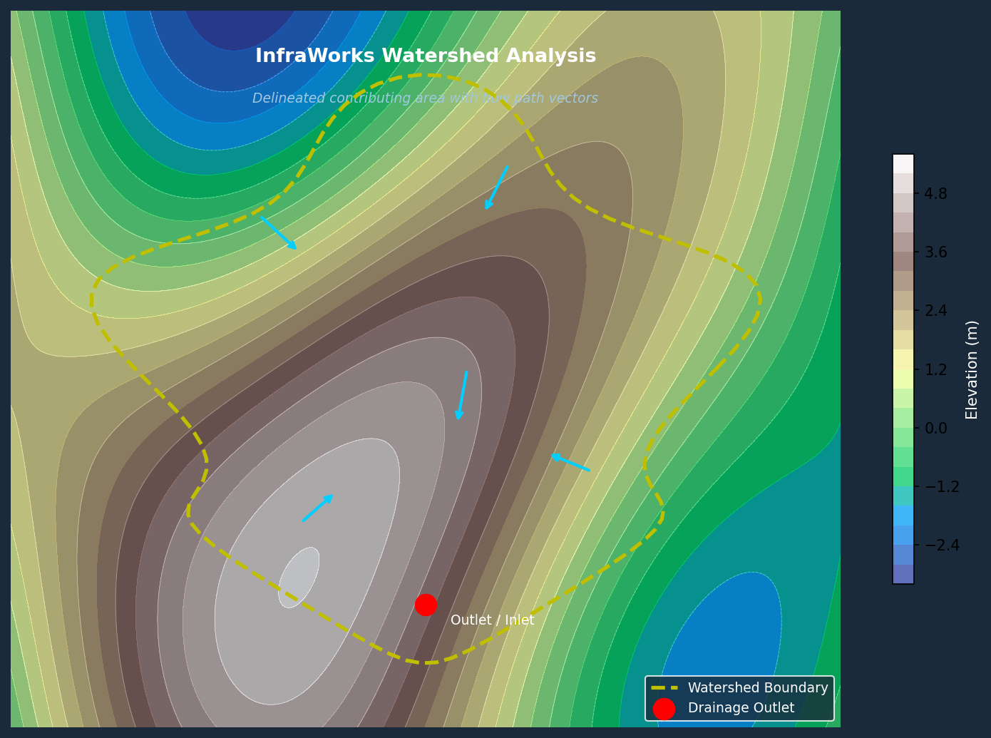
Terrain Themes allow designers to overlay the site surface with color-coded slope, aspect, or elevation maps. This immediately reveals natural drainage divides, low-lying ponding areas, and the general direction of overland flow—critical inputs for determining where inlets, culverts, and detention basins will be needed.

Watershed Analysis goes further by delineating contributing drainage areas for any selected point on the terrain or along a road alignment. The tool calculates approximate runoff volumes using the rational method, giving engineers a defensible basis for preliminary pipe sizing before committing to detailed design. For corridor projects, watershed analysis can be run iteratively along the entire alignment to identify every cross-drainage structure location.
The output of this stage is a conceptual drainage layout—structure locations, approximate pipe diameters, and watershed boundaries—that travels downstream into Civil 3D via IMX or File Geodatabase (FGDB) export.
Stage 2: Network Layout and Catchment Delineation in Civil 3D
Civil 3D receives the InfraWorks terrain and preliminary network as a starting point for detailed design. The quality of the surface model at this stage is critical: a regularly triangulated TIN with well-defined breaklines along curbs, swales, and ridgelines is required to ensure that automatic catchment delineation produces accurate results.
Key Civil 3D tasks in the drainage workflow include:
- Pipe Network Creation: Structures and pipes are placed using the InfraWorks layout as a guide, with part families mapped to match InfoDrainage's component library to ensure clean export.
- Catchment Delineation: Civil 3D can automatically delineate catchments from the surface model or accept manually drawn closed polylines. Each catchment is assigned hydrologic properties—Time of Concentration (Tc), runoff method (Rational, SCS, etc.), and land-use coefficients.
- Flow Path Definition: Overland and gutter flow paths are traced from each catchment to its receiving inlet, establishing the hydrologic connectivity that InfoDrainage will use for routing calculations.
Once the network and catchments are configured, the model is exported to InfoDrainage via an IDDX file. This format preserves pipe geometry, structure elevations, catchment boundaries, and hydrologic parameters in a single transfer, eliminating manual re-entry.
Stage 3: Hydraulic Analysis and Regulatory Reporting in InfoDrainage
InfoDrainage is where the engineering analysis occurs. It accepts the Civil 3D export and provides capabilities that go well beyond what either InfraWorks or Civil 3D can offer independently:
Machine Learning Deluge Tool: This feature applies synthetic rainfall to the site surface using a machine-learning-derived flow model to identify ponding locations and channeling patterns. The output guides optimal placement of Stormwater Control Measures (SCMs) such as bioretention cells, permeable pavement, and detention basins—before any detailed sizing is performed.
Automated Hydrologic Calculations: InfoDrainage captures land-use and soil-type data to automatically compute SCS Composite Curve Numbers, runoff coefficients, and percentage impervious area for each catchment. This eliminates a common source of manual error and ensures consistency across large, multi-catchment networks.
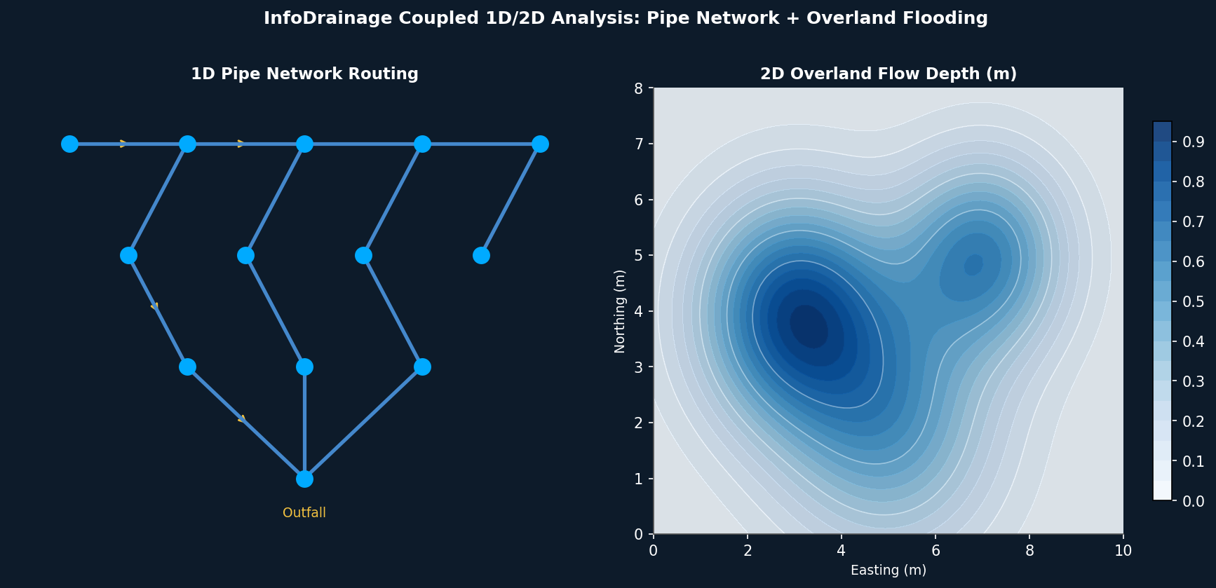
Coupled 1D/2D Analysis: For urban flooding assessments, InfoDrainage can run coupled one-dimensional pipe network routing alongside two-dimensional overland flow modeling. This captures the interaction between in-pipe flow and surface flooding—essential for demonstrating regulatory compliance with local flood frequency standards (e.g., 10-year, 100-year return periods).
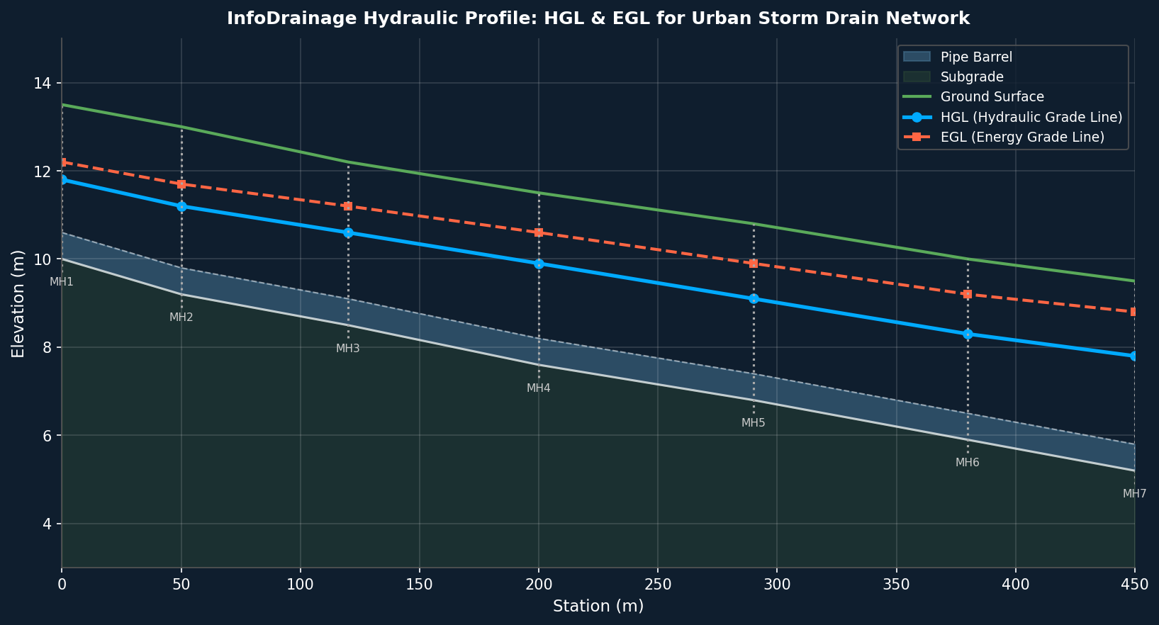
Flexible Reporting: The 2025.1 release introduced customizable report templates that combine inputs, simulation outputs, and hydraulic results (HGL, EGL, freeboard, maximum velocity) into a single exportable table. This significantly reduces documentation time for permit submissions.
Round-Trip Data Synchronization
A defining feature of this workflow is its bi-directionality. After analysis in InfoDrainage, refined catchment boundaries, updated pipe sizes, and hydraulic results—including Hydraulic Grade Line (HGL), Energy Grade Line (EGL), maximum flow rates, and maximum velocities—can be pushed back into Civil 3D via the InfoDrainage/Civil 3D ribbon. Civil 3D pipe network properties are updated automatically, keeping the construction drawing model synchronized with the hydraulic model throughout the design iteration cycle.
This round-trip capability is particularly valuable during design review, when regulatory agencies or peer reviewers request changes to pipe sizing or inlet locations. Engineers can make the change in InfoDrainage, re-run the analysis, and propagate the update to Civil 3D without rebuilding the network from scratch.
Practical Recommendations
- Invest in surface quality early. Errors in the Civil 3D TIN propagate directly into catchment areas and Tc calculations. Spend time defining breaklines before delineating catchments.
- Map part families before export. Mismatched pipe and structure types between Civil 3D and InfoDrainage are the most common cause of failed IDDX imports. Verify the part mapping table before exporting.
- Use the ML Deluge tool before sizing. Running the machine learning surface flow analysis before committing to SCM locations can prevent costly redesigns later in the project.
- Leverage flexible reporting for agency submissions. Configure InfoDrainage report templates to match the specific table formats required by your local stormwater authority, reducing back-and-forth during permit review.