
SPICE Circuit Simulation: Transient Analysis for Power Supply Design
Power supply design demands rigorous verification of dynamic behavior under varying load conditions, startup sequences, and fault scenarios. SPICE (Simulation Program with Integrated Circuit Emphasis) transient analysis provides engineers with the capability to predict time-domain circuit responses with high accuracy, enabling optimization before physical prototyping. This article explores advanced transient analysis techniques specifically tailored for switch-mode power supply (SMPS) design.
Understanding Transient Analysis in SPICE
Transient analysis solves the time-dependent differential equations governing circuit behavior, computing voltage and current waveforms at each node and branch. Unlike DC operating point or AC small-signal analysis, transient simulation captures nonlinear effects including switching transitions, magnetic saturation, and thermal dynamics. For power electronics, this capability is essential to evaluate:
- Startup behavior: Soft-start circuits, inrush current limiting, and output voltage ramp rates
- Load transient response: Output voltage deviation and recovery time when load current changes abruptly
- Loop stability: Phase margin and gain margin verification through step response analysis
- Efficiency calculation: Switching losses, conduction losses, and overall power conversion efficiency
Critical Simulation Parameters
Achieving accurate and efficient transient simulations requires careful configuration of solver parameters. The maximum timestep (TMAX) controls temporal resolution—too large and switching edges are poorly resolved; too small and simulation time becomes prohibitive. For typical SMPS operating at 100-500 kHz, setting TMAX to 1/100th of the switching period provides adequate resolution.

The RELTOL (relative tolerance) parameter governs convergence criteria. Default values of 0.001 work for most circuits, but tighter tolerances (0.0001) may be necessary for high-precision analog circuits or when measuring small ripple voltages. Conversely, relaxing RELTOL can accelerate simulation of robust digital circuits.
Modeling Realistic Components

Generic SPICE models often fail to capture real-world component behavior. For power MOSFETs, manufacturers provide detailed subcircuit models incorporating:
- Gate charge characteristics: Qg, Qgd, and Qgs parameters affecting switching speed
- Body diode reverse recovery: Trr and Qrr parameters critical for hard-switching topologies
- On-resistance temperature coefficient: RDS(on) variation with junction temperature
Magnetic components require special attention. Simple inductor models with constant inductance and series resistance are inadequate for high-current applications. Advanced models should include:
- Core saturation: Inductance reduction at high flux density using behavioral modeling
- AC resistance: Skin effect and proximity effect losses at switching frequencies
- Core losses: Steinmetz equation implementation for frequency-dependent losses
For capacitors, equivalent series resistance (ESR) and equivalent series inductance (ESL) significantly impact high-frequency performance. Ceramic capacitors exhibit voltage-dependent capacitance that must be modeled for accurate output ripple prediction.
Practical Simulation Workflow

A systematic approach to power supply transient analysis begins with DC operating point verification. Confirm that all node voltages and device currents match hand calculations before proceeding to transient simulation. This step catches modeling errors early.
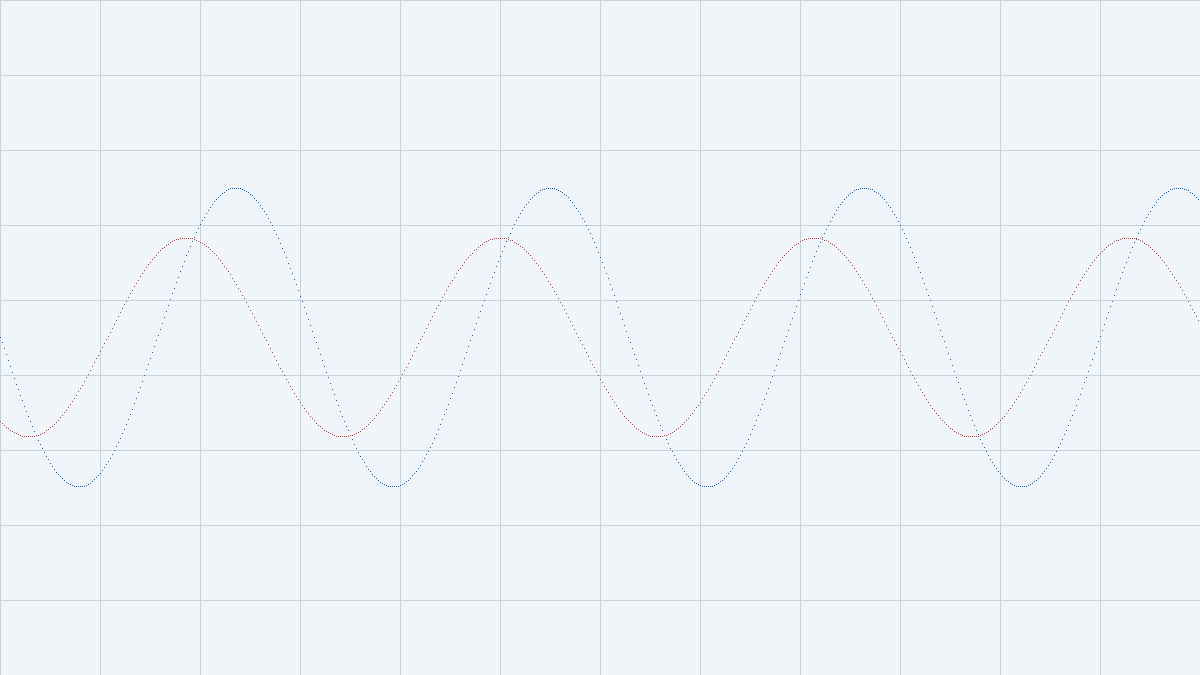
Next, simulate steady-state operation for multiple switching cycles. Monitor key waveforms including switch node voltage, inductor current, and output voltage ripple. Verify that the control loop maintains regulation and that no unexpected oscillations occur.
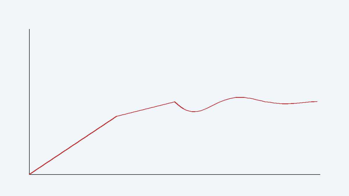
Load transient testing follows, applying step changes in load current from minimum to maximum. Measure output voltage undershoot/overshoot and recovery time. These metrics directly correlate to control loop bandwidth and output capacitance adequacy.
Finally, conduct worst-case analysis by sweeping component tolerances and operating conditions. Monte Carlo analysis with statistical component variation reveals design robustness and identifies critical parameters requiring tighter specifications.
Advanced Techniques: Mixed-Mode Simulation
Modern power supplies integrate analog control loops with digital state machines for sequencing, protection, and communication. Mixed-mode simulation combines SPICE analog solvers with event-driven digital simulation, enabling co-verification of the complete system.
For example, a digitally-controlled buck converter might use a microcontroller ADC to sample output voltage, execute a PID algorithm, and generate PWM signals. Mixed-mode simulation allows verification of ADC quantization effects, computational delays, and PWM resolution limitations—factors that purely analog simulation cannot capture.
Conclusion
SPICE transient analysis remains the cornerstone of power supply design verification, providing insights into dynamic behavior that analytical methods cannot match. By carefully selecting component models, configuring solver parameters, and following systematic simulation workflows, engineers can achieve high confidence in design performance before committing to hardware. As power electronics continue to push boundaries in efficiency and power density, mastery of advanced SPICE techniques becomes increasingly valuable.
Further Resources
- LTspice XVII: Free SPICE simulator optimized for power electronics (Analog Devices)
- SPICE Model Libraries: Comprehensive component models (Infineon)
- Power Supply Design Seminars: In-depth application notes (Texas Instruments)
- IEEE Power Electronics Society: Technical publications and standards (IEEE PELS)