
Synopsys PrimeSim HSPICE: Advanced Noise Analysis for High-Speed SerDes and Memory Interface Design
Introduction
As data rates push beyond 56 Gbps in modern SerDes links and DDR5/LPDDR5 memory interfaces, noise analysis has become a first-order design constraint rather than a post-layout afterthought. Synopsys PrimeSim HSPICE — the industry's gold-standard SPICE simulator — provides a comprehensive suite of noise analysis capabilities that go well beyond the basic .NOISE statement familiar to most engineers. This article examines HSPICE's advanced noise analysis workflow, focusing on the techniques that matter most for high-speed digital interface design: jitter decomposition, phase noise simulation, and noise-aware eye diagram generation.
Why Standard SPICE Noise Analysis Falls Short
Traditional .NOISE analysis in SPICE computes the equivalent input-referred noise voltage or current at a single frequency point, which is adequate for low-frequency analog circuits but insufficient for multi-gigabit interfaces. The limitations are significant:
- Frequency-domain only: Standard noise sweeps do not capture time-domain jitter contributions from individual noise sources.
- No phase noise decomposition: Oscillator and PLL phase noise requires dedicated analysis modes.
- Ignores nonlinear mixing: At high frequencies, noise folds back through nonlinear device behavior, which linear noise analysis cannot model.
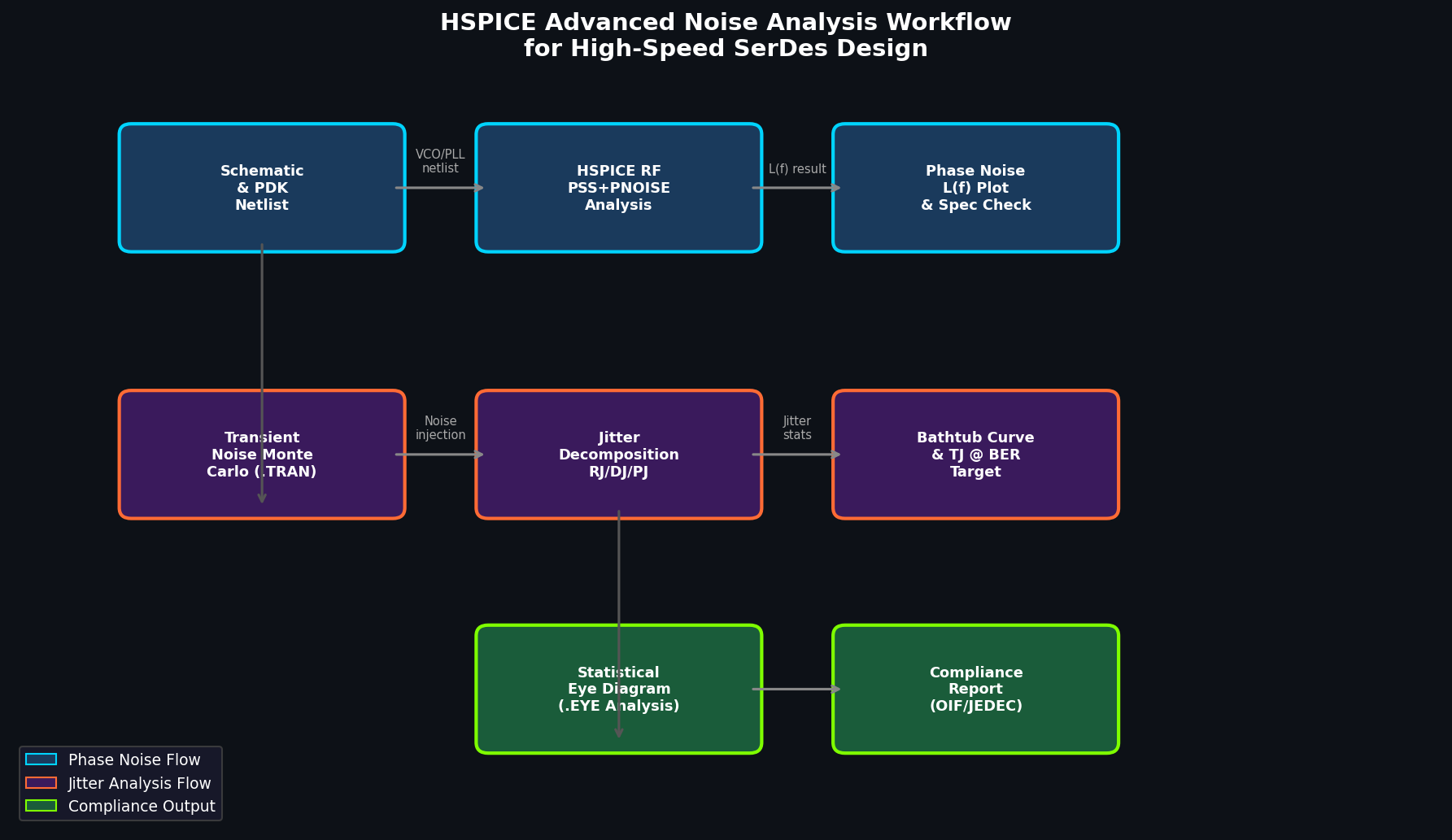
HSPICE addresses these gaps through three specialized analysis modes: HSPICE RF noise, HSPICE Noise Spectral Density (NSD) with transient noise injection, and the HSPICE Eye analysis framework.
Transient Noise Analysis: Capturing Jitter at the Source
HSPICE's transient noise (.TRAN with TRANOISE option) injects statistically correct noise sources — thermal, shot, and flicker — directly into the time-domain simulation. This enables engineers to observe how individual device noise sources translate into timing jitter at the output.
Key Setup Parameters
.OPTIONS TRANOISE=1 NOISESCALE=1.0 SEED=12345
.TRAN 1ps 10ns SWEEP MONTE=200TRANOISE=1: Enables stochastic noise injection during transient simulation.NOISESCALE: Scales the noise power spectral density; set to 1.0 for physical accuracy.SEED: Controls the random number generator for reproducible Monte Carlo runs.SWEEP MONTE=200: Runs 200 Monte Carlo iterations to build a statistically meaningful jitter distribution.
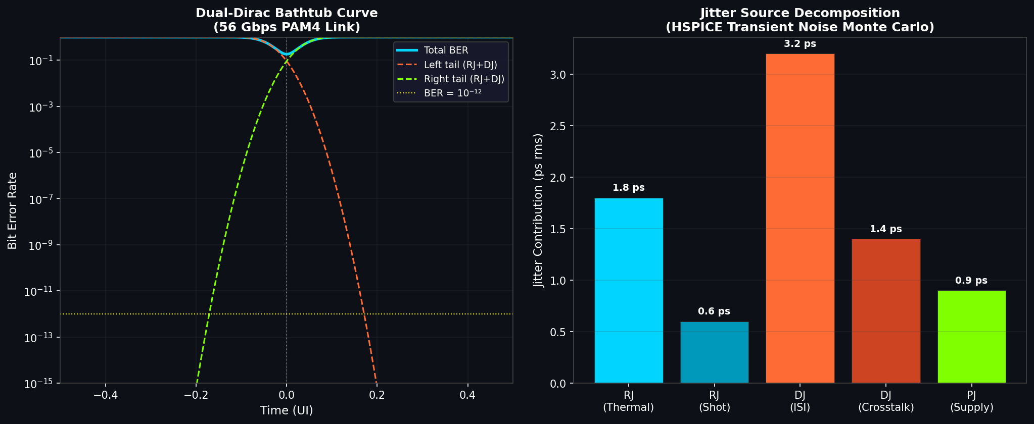
Jitter Decomposition Workflow
After running transient noise Monte Carlo, HSPICE's post-processing scripts (hspice_jitter.py or the WaveView GUI) decompose total jitter (TJ) into:
- Random Jitter (RJ): Gaussian-distributed, arising from thermal and shot noise in resistors, transistors, and passive components.
- Deterministic Jitter (DJ): Bounded, systematic contributions from ISI, crosstalk, and supply noise coupling.
- Periodic Jitter (PJ): Correlated with a specific frequency, typically from switching regulators or reference clock spurs.
The decomposition uses the dual-Dirac model, which is the standard methodology in JEDEC and OIF-CEI specifications. HSPICE outputs TJ at a target BER (e.g., 10⁻¹²) directly, enabling compliance checking against interface specifications without manual extrapolation.
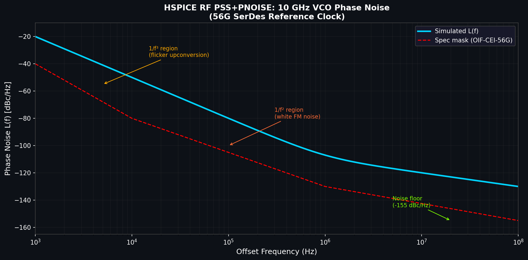
Phase Noise Simulation with HSPICE RF
For PLL and VCO design within SerDes transceivers, HSPICE RF's Periodic Steady-State (PSS) + Periodic Noise (PNOISE) analysis provides rigorous phase noise characterization.
PSS + PNOISE Setup
.HBAC PNOISE FUND=10GHz NHARMS=20 PNOISEFREQ=1kHz,100MHz,100
+ PNOISETYPE=PMFUND: Fundamental oscillation frequency of the VCO.NHARMS: Number of harmonics to include; 20 is typically sufficient for accurate noise folding.PNOISEFREQ: Offset frequency range for the phase noise plot (1 kHz to 100 MHz here).PNOISETYPE=PM: Requests phase modulation noise (L(f) in dBc/Hz).
The PNOISE analysis correctly accounts for noise upconversion through the nonlinear VCO core — a critical effect that linear noise analysis misses entirely. Flicker noise from the tail current source, for example, appears as a 1/f³ slope in the close-in phase noise, and HSPICE RF captures this accurately.
Practical Tip: Noise Source Contribution Analysis
HSPICE RF can rank individual device noise contributions to the total phase noise at any offset frequency:
.MEASURE PNOISE NOISECONTRIB AT=1MHzThis output identifies the dominant noise sources — often the tail current transistor or the load resistors — enabling targeted design optimization before layout.
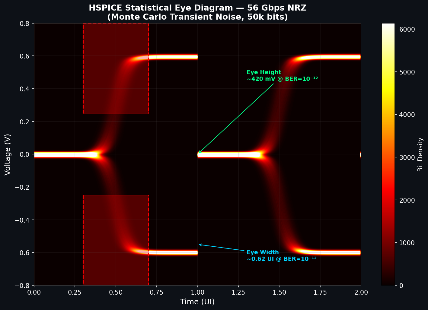
Noise-Aware Eye Diagram Generation
HSPICE's .EYE analysis integrates transient noise simulation with statistical eye diagram construction, producing eye diagrams that include the effects of both deterministic and random noise sources.
Eye Analysis Configuration
.EYE V(out) DATARATE=56Gbps EYEPOINTS=1e6
+ JITTERMODEL=DUALDIREC BER=1e-12
+ NOISEBW=28GHzDATARATE: Sets the UI (unit interval) for eye mask alignment.EYEPOINTS: Number of simulated bit transitions; 10⁶ provides good BER extrapolation accuracy.JITTERMODEL=DUALDIREC: Applies the dual-Dirac jitter model for BER extrapolation.BER: Target bit error rate for eye opening measurement.NOISEBW: Noise bandwidth, typically set to half the data rate for Nyquist-limited channels.
The resulting eye diagram reports eye height (mV), eye width (ps), and the bathtub curve — all at the specified BER — making it directly comparable to compliance test results from a real-time oscilloscope.
Best Practices for High-Speed Interface Noise Analysis
- Use foundry-certified PDKs: Noise model accuracy depends entirely on the BSIM4/BSIM-CMG model parameters provided by the foundry. Always use the latest certified PDK release.
- Validate with bench measurements: Correlate HSPICE phase noise predictions against a spectrum analyzer measurement on a silicon prototype before trusting simulation for design decisions.
- Separate RJ and DJ budgets early: Allocate jitter budgets at the architecture level using HSPICE's decomposition output, then track compliance through each design phase.
- Leverage distributed simulation: HSPICE's
HSPICE-MTmulti-threading andHSPICE-LPdistributed computing modes reduce Monte Carlo runtimes from hours to minutes on modern compute clusters. - Cross-check with system-level tools: Use HSPICE noise results as inputs to Synopsys SystemSI or Keysight ADS for full channel simulation, ensuring that device-level noise translates correctly to link-level BER.
Integration with Synopsys Design Flow
HSPICE noise analysis integrates natively with:
- Synopsys Custom Compiler: Schematic-driven HSPICE netlisting with noise analysis setup through the GUI.
- Synopsys StarRC: Parasitic extraction feeds directly into HSPICE for post-layout noise simulation.
- Synopsys PrimeWave: Unified waveform viewer and measurement framework for noise and jitter results.
The hspice_noise_report.tcl script, available in the PrimeSim installation, automates the extraction of RJ, DJ, TJ, and phase noise metrics into a structured CSV report suitable for design review documentation.
Conclusion
HSPICE's advanced noise analysis capabilities — transient noise Monte Carlo, PSS/PNOISE for phase noise, and statistical eye diagram generation — provide the analytical depth required for modern high-speed interface design. By moving beyond simple .NOISE sweeps and leveraging HSPICE's full noise analysis suite, design teams can identify dominant jitter contributors early, validate compliance margins at target BER levels, and reduce costly silicon respins. For engineers working on 56G/112G SerDes, DDR5, or LPDDR5 interfaces, mastering these HSPICE noise analysis workflows is an essential competency.